Toyota Sequoia (2005). Manual — part 473

–
DIAGNOSTICS
BODY CONTROL SYSTEM
DI–1687
1881
WIRELESS DOOR LOCK CONTROL
Symptom
Suspected Area
See page
All functions of wireless door lock control system do not operate.
1. Transmitter
2. Wireless door lock receiver circuit
3. Key unlock warning switch circuit
4. Body ECU
Lock (or unlock) function does not operate.
1. Door unlock detection switch circuit (Driver’s)
(Passenger’s)
(Rear Door)
(Back Door)
2. Any door ECU
3. Body ECU
Automatic lock function operates even if any door is opened within
30 seconds after all doors are unlocked by wireless door lock
control system.
1. Door courtesy light switch circuit
2. Any door ECU
3. Body ECU
Wireless door lock function operates, but the buzzer does not
sound.
1. Wireless door lock buzzer circuit
2. Body ECU
Buzzer sounds, but wireless door lock function does not operate.
Body ECU
REAR WIPER AND WASHER
Symptom
Suspected Area
See page
Rear wiper does not operate.
1. Rear wiper switch and motor circuit
2. Body ECU
Rear washer does not operate.
1. Rear washer switch and motor circuit
2. Body ECU
LIGHT CONTROL
Symptom
Suspected Area
See page
Automatic light control does not operate.
1. Automatic light control sensor circuit
2. Light control switch circuit
3. Body ECU
Auto turn–off does not operate.
1. Door courtesy light switch circuit (Driver side)
2. Ignition switch
3. Driver door ECU
4. Body ECU
Daytime running light function does not operate.
1. Daytime running light relay circuit
2. Parking brake switch circuit
3. Body ECU
FOG LIGHT
Symptom
Suspected Area
See page
Fog lights do not come on.
1. Bulb
2. FOG fuse
3. Fog light relay and switch circuit
4. Body ECU
–
OTHERS
Symptom
Suspected Area
See page
Illuminated entry function does not operate.
1. Illumination circuit
2. Body ECU
All functions of the body control system do not operate.
1. Power source circuit
2. Body ECU
Remote control mirror does not operate.
(w/ Driving position memory)
1. Remote control mirror switch circuit
2. Driving position memory switch circuit
3. Body ECU
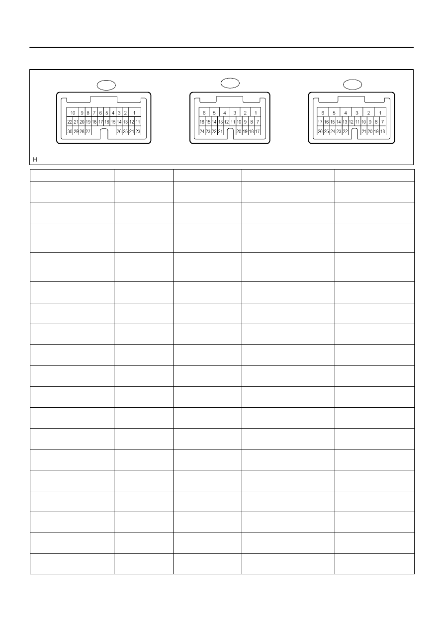
DI1OG–31
I27698
B5
B6
B7
BODY CONTROL ECU:
DI–1688
–
DIAGNOSTICS
BODY CONTROL SYSTEM
1882
TERMINALS OF ECU
Symbols (Terminals No.)
Wiring Color
Terminal Description
Condition
Specified Condition
KSW – GND1
(B5–13 – B6–6)
Y–G – W–B
Key unlock warning
switch signal
Key unlock warning switch ON
(Key inserted)
Below 1 V
KSW – GND1
(B5–13 – B6–6)
Y–G – W–B
Key unlock warning
switch signal
Key unlock warning switch OFF
(Key not inserted)
10 to 14 V
KSW2 – GND1
(B5–15 – B6–6)
Y–G – W–B
Key unlock warning
switch signal (Immobi-
lizer)
Key unlock warning switch ON
(Key inserted)
Below 1 V
KSW2 – GND1
(B5–15 – B6–6)
Y–G – W–B
Key unlock warning
switch signal (Immobi-
lizer)
Key unlock warning switch OFF
(Key not inserted)
10 to 14 V
HR – GND1
(B7–18 – B6–6)
W–R – W–B
Horn switch signal
Horn switch ON
Below 1 V
HR – GND1
(B7–18 – B6–6)
W–R – W–B
Horn switch signal
Horn switch OFF
10 to 14 V
BDN – GND1
(B6–15 – B6–6)
P–L – W–B
Back door power win-
dow motor (DOWN)
Back door power window switch
DOWN position
Below 1 V
BDN – GND1
(B6–15 – B6–6)
P–L – W–B
Back door power win-
dow motor (DOWN)
Back door power window switch
OFF or UP position
10 to 14 V
BUP – GND1
(B6–14 – B6–6)
W – W–B
Back door power win-
dow motor (UP)
Back door power window switch
UP position
Below 1 V
BUP – GND1
(B6–14 – B6–6)
W – W–B
Back door power win-
dow motor (UP)
Back door power window switch
OFF or DOWN position
10 to 14 V
ACC – GND1
(B7–10 – B6–6)
GR – W–B
Ignition switch (ACC)
Ignition switch OFF
Below 1 V
ACC – GND1
(B7–10 – B6–6)
GR – W–B
Ignition switch (ACC)
Ignition switch ACC or ON
10 to 14 V
BECU – GND1
(B6–5 – B6–6)
W–R – W–B
Battery
Always
10 to 14 V
RLCY – GND1
(B7–7 – B6–6)
R–W – W–B
Courtesy light switch
(Rear LH)
Rear LH door courtesy light
switch ON (Open)
Below 1 V
RLCY – GND1
(B7–7 – B6–6)
R–W – W–B
Courtesy light switch
(Rear LH)
Rear LH door courtesy light
switch OFF (Closed)
10 to 14 V
RRCY – GND1
(B5–8 – B6–6)
R–W – W–B
Courtesy light switch
(Rear RH)
Rear RH door courtesy light
switch ON (Open)
Below 1 V
RRCY – GND1
(B5–8 – B6–6)
R–W – W–B
Courtesy light switch
(Rear RH)
Rear RH door courtesy light
switch OFF (Closed)
10 to 14 V
PCTY – GND1
(B5–22 – B6–6)
LG–B – W–B
Courtesy light switch
(Front RH)
Passenger door courtesy light
switch ON (Open)
Below 1 V

–
DIAGNOSTICS
BODY CONTROL SYSTEM
DI–1689
1883
PCTY – GND1
(B5–22 – B6–6)
LG–B – W–B
Courtesy light switch
(Front RH)
Passenger door courtesy light
switch OFF (Closed)
10 to 14 V
LSWL – GND1
(B7–24 – B6–6)
P–L – W–B
Door unlock detection
switch (Rear LH)
Rear LH door unlock detection
switch ON (Unlocked)
Below 1 V
LSWL – GND1
(B7–24 – B6–6)
P–L – W–B
Door unlock detection
switch (Rear LH)
Rear LH door unlock detection
switch OFF (Locked)
10 to 14 V
DCTY – GND1
(B7–12 – B6–6)
GR–R – W–B
Courtesy light switch
(Front LH)
Driver door courtesy light switch
ON (Open)
Below 1 V
DCTY – GND1
(B7–12 – B6–6)
GR–R – W–B
Courtesy light switch
(Front LH)
Driver door courtesy light switch
OFF (Closed)
10 to 14 V
LSWR – GND1
(B5–21 – B6–6)
P–B – W–B
Door unlock detection
switch (Rear RH)
Rear RH door unlock detection
switch ON (Unlocked)
Below 1 V
LSWR – GND1
(B5–21 – B6–6)
P–B – W–B
Door unlock detection
switch (Rear RH)
Rear RH door unlock detection
switch OFF (Locked)
10 to 14 V
HORN – GND1
(B5–26 – B6–6)
B–Y – W–B
Horn switch signal
Horn switch OFF
10 to 14 V
HORN – GND1
(B5–26 – B6–6)
B–Y – W–B
Horn switch signal
Horn switch ON
Below 1 V
BDR – GND1
(B6–2 – B6–6)
L–W – W–B
Battery
Always
10 to 14 V
GND1 – Body ground
(B6–6 – Body ground)
W–B – Body ground
Ground
Always
Below 1 V
RWLS – GND1
(B5–6 – B6–6)
Y–B – W–B
Rear wiper switch sig-
nal (ON)
Rear wiper switch ON
Below 1 V
RWLS – GND1
(B5–6 – B6–6)
Y–B – W–B
Rear wiper switch sig-
nal (ON)
Rear wiper switch OFF or INT
10 to 14 V
RWC1 – GND1
(B5–7 – B6–6)
G–B – W–B
Rear wiper switch sig-
nal (INT)
Rear wiper switch INT
Below 1 V
RWC1 – GND1
(B5–7 – B6–6)
G–B – W–B
Rear wiper switch sig-
nal (INT)
Rear wiper switch OFF
10 to 14 V
ACTD – GND1
(B7–2 – B6–6)
R–B – W–B
Door lock motor (Front
LH)
Power door lock not operating or
operating to UNLOCK
Below 1 V
ACTD – GND1
(B7–2 – B6–6)
R–B – W–B
Door lock motor (Front
LH)
Power door lock not operating to
LOCK
10 to 14 V
IND – GND1
(B5–16 – B6–6)
GR – W–B
Security indicator light
Security indicator is off
Below 1 V
IND – GND1
(B5–16 – B6–6)
GR – W–B
Security indicator light
Security indicator light is on
10 to 14 V
SH – GND1
(B7–1 – B6–6)
R–G – W–B
Theft deterrent horn
signal
Security horn does not sound
Below 1 V
SH – GND1
(B7–1 – B6–6)
R–G – W–B
Theft deterrent horn
signal
Security horn sounds
10 to 14 V
HRLY – GND1
(B7–8 – B6–6)
LG–R – W–B
HEAD relay signal
HEAD relay ON
Below 1 V
HRLY – GND1
(B7–8 – B6–6)
LG–R – W–B
HEAD relay signal
HEAD relay OFF
10 to 14 V
TRLY – GND1
(B7–11 – B6–6)
LG – W–B
Taillight relay signal
Taillight relay ON
Below 1 V
TRLY – GND1
(B7–11 – B6–6)
LG – W–B
Taillight relay signal
Taillight relay OFF
10 to 14 V

DI–1690
–
DIAGNOSTICS
BODY CONTROL SYSTEM
1884
HCTY – GND1
(B7–14 – B6–6)
L–W – W–B
Engine hood courtesy
switch signal
Hood courtesy light switch ON
(Open)
Below 1 V
HCTY – GND1
(B7–14 – B6–6)
L–W – W–B
Engine hood courtesy
switch signal
Hood courtesy light switch OFF
(Close)
10 to 14 V
WIG – GND1
(B7–5 – B6–6)
L–Y – W–B
Ignition Switch (IG)
Ignition switch LOCK
Below 1 V
WIG – GND1
(B7–5 – B6–6)
L–Y – W–B
Ignition Switch (IG)
Ignition switch ON
10 to 14 V
IG – GND1
(B7–6 – B6–6)
B–R – W–B
Ignition Switch (IG)
Ignition switch LOCK
Below 1 V
IG – GND1
(B7–6 – B6–6)
B–R – W–B
Ignition Switch (IG)
Ignition switch ON
10 to 14 V
RWW – GND1
(B7–4 – B6–6)
G–B – W–B
Rear washer switch
(ON)
Rear washer switch ON
Below 1 V
RWW – GND1
(B7–4 – B6–6)
G–B – W–B
Rear washer switch
(ON)
Rear washer switch OFF
10 to 14 V
ACT+ – GND1
(B5–1 – B6–6)
L–R – W–B
Door lock motor (UN-
LOCK)
Power door lock not operating or
operating to UNLOCK
Below 1 V
ACT+ – GND1
(B5–1 – B6–6)
L–R – W–B
Door lock motor (UN-
LOCK)
Power door lock operating to
LOCK
10 to 14 V
ACT– – GND1
(B5–10 – B6–6)
L–B – W–B
Door lock motor
(LOCK)
Power door lock not operating or
operating to LOCK
Below 1 V
ACT– – GND1
(B5–10 – B6–6)
L–B – W–B
Door lock motor
(LOCK)
Power door lock operating to UN-
LOCK twice
10 to 14 V
MPX1
(B7–22)
W–L
Multiplex communica-
tion signal
Multiplex communication circuit
–
MPX2 (*2)
(B5–24)
L–Y
Multiplex communica-
tion signal
Multiplex communication circuit
–
MPX3
(B7–20)
G–O
Multiplex communica-
tion signal
Multiplex communication circuit
–
ILE – GND1
(B7–3 – B6–6)
W – W–B
Illumination
Map Light is off
Below 1 V
ILE – GND1
(B7–3 – B6–6)
W – W–B
Illumination
Map Light is on
10 to 14 V
PRG – GND1
(B5–5 – B6–6)
V – W–B
Wireless transmitter
signal ground
Wireless door look receiver com-
munication circuit
–
RDA – GND1
(B5–4 – B6–6)
R–G – W–B
Wireless transmitter
signal input
Wireless door lock control sys-
tem is operated
Below 1 V
RDA – GND1
(B5–4 – B6–6)
R–G – W–B
Wireless transmitter
signal input
Wireless door lock control sys-
tem is not operated
10 to 14 V
HU – GND1
(B6–11 – B6–6)
Y–R – W–B
Headlight dimmer
switch (HI)
Headlight dimmer switch position
is Hi beam or FLASH
Below 1 V
HU – GND1
(B6–11 – B6–6)
Y–R – W–B
Headlight dimmer
switch (HI)
Headlight dimmer switch position
is not Hi beam or FLASH
10 to 14 V
HF – GND1
(B6–8 – B6–6)
R–L – W–B
Headlight dimmer
switch (FLASH)
Headlight dimmer switch position
is FLASH
Below 1 V
HF – GND1
(B6–8 – B6–6)
R–L – W–B
Headlight dimmer
switch (FLASH)
Headlight dimmer switch position
is not FLASH
10 to 14 V
TAIL – GND1
(B6–7 – B6–6)
G – W–B
Light control switch
(TAIL)
Light control switch TAIL or
HEAD
Below 1 V
Нет комментариевНе стесняйтесь поделиться с нами вашим ценным мнением.
Текст