Toyota 86 (2023 year). Manual in english — page 5
77
1-3. Emergency assistance
1
For safety and secu
rity
illuminate and then turn off.
Then, the green indicator light
will illuminate to indicate that the
service is active.
The following indicator light pat-
terns indicate specific system
usage conditions:
Green indicator light on =
Active service
Green indicator light flashing
= Safety Connect call in pro-
cess
Red indicator light on (except
at vehicle start-up) = System
malfunction (contact your Toy-
ota dealer)
No indicator light (off) =
Safety Connect service not
active
■
Automatic Collision Notifi-
cation
In case of either airbag deploy-
ment or severe rear-end colli-
sion, the system is designed to
automatically call the response
center. The responding agent
receives the vehicle’s location
and attempts to speak with the
vehicle occupants to assess the
level of emergency. If the occu-
pants are unable to communi-
cate, the agent automatically
treats the call as an emergency,
contacts the nearest emer-
gency services provider to
describe the situation, and
requests that assistance be sent
to the location.
■
Stolen Vehicle Location
If your vehicle is stolen, Safety
Connect can work with local
authorities to assist them in
locating and recovering the
vehicle. After filing a police
report, call the Customer Experi-
ence Center at 1-800-331-4331
in the United States or
1-888-869-6828 in Canada, and
follow the prompts for Safety
Connect to initiate this service.
In addition to assisting law
enforcement with recovery of a
stolen vehicle, Safety-Con-
nect-equipped vehicle location
data may, under certain circum-
stances, be shared with third
parties to locate your vehicle.
Further information is available
at Toyota.com in the United
States and Toyota.ca in Canada.
■
Emergency Assistance But-
ton (“SOS” button)
In the event of an emergency on
the road, push the “SOS” button
to reach the Safety Connect
response center. The answer-
ing agent will determine your
vehicle’s location, assess the
emergency, and dispatch the
necessary assistance required.
If the “SOS” button is pressed unin-
tentionally, press and hold the
“SOS” button for approximately 2
seconds or more or operate the
Safety Connect services
78
1-3. Emergency assistance
connection screen on the multime-
dia system screen to cancel the
connection to a response-center
agent.
■
Enhanced Roadside Assis-
tance (“i” button)
Enhanced Roadside Assistance
adds GPS data to the already
included warranty-based Toyota
roadside service.
Subscribers can press the “i”
button on the interior lights to
contact a Roadside Assistance
provider, who can help with a
wide range of needs, such as:
towing, flat tire, fuel delivery, etc.
For a description of the
Enhanced Roadside Assistance
services and their limitations,
please see the Safety Connect
Terms and Conditions, which
are available at Toyota.com in
the United States and Toyota.ca
in Canada.
If the “i” button on the interior
lights is pressed unintentionally,
press and hold the “i” button for
approximately 2 seconds or
more or operate the connection
screen on the multimedia sys-
tem screen to cancel the con-
nection to a roadside assistance
provider.
Important! Read this informa-
tion before using Safety Con-
nect.
■
Exposure to radio fre-
quency signals
The Safety Connect system
installed in your vehicle is a
low-power radio transmitter and
receiver. It receives and also
sends out radio frequency (RF)
signals.
In August 1996, the Federal
Communications Commission
(FCC) adopted RF exposure
guidelines with safety levels for
mobile wireless phones. Those
guidelines are consistent with
the safety standards previously
set by the following U.S. and
international standards bodies.
ANSI (American National
Standards Institute) C95.1
[1992]
NCRP (National Council on
Radiation Protection and
Measurement) Report 86
[1986]
ICNIRP (International Com-
mission on Non-Ionizing Radi-
ation Protection) [1996]
Those standards were based on
comprehensive and periodic
evaluations of the relevant sci-
entific literature. Over 120 scien-
tists, engineers, and physicians
from universities, and govern-
ment health agencies and
industries reviewed the avail-
able body of research to
develop the ANSI Standard
Safety information for
Safety Connect
79
1-3. Emergency assistance
1
For safety and secu
rity
(C95.1).
The design of Safety Connect
complies with the FCC guide-
lines in addition to those stan-
dards.

80
1-4. Theft deterrent system
1-4.Theft deterrent system
The indicator light flashes after
the engine switch has been
turned off to indicate that the
system is operating.
The indicator light stops flashing
after the engine switch has been
turned to ACC or ON to indicate
that the system has been can-
celed.
■
System maintenance
The vehicle has a mainte-
nance-free type engine immobilizer
system.
■
Conditions that may cause the
system to malfunction
●
If the grip portion of the key is in
contact with a metallic object
●
If the key is in close proximity to or
touching a key registered to the
security system (key with a built-in
transponder chip) of another vehi-
cle
Engine immobilizer
system
The vehicle’s keys have
built-in transponder chips
that prevent the engine from
starting if a key has not
been previously registered
in the vehicle’s on-board
computer.
Never leave the keys inside
the vehicle when you leave
the vehicle.
This system is designed to
help prevent vehicle theft
but does not guarantee
absolute security against all
vehicle thefts.
Operating the system
NOTICE
■
To ensure the system oper-
ates correctly
Do not modify or remove the sys-
tem. If modified or removed, the
proper operation of the system
cannot be guaranteed.

81
1-4. Theft deterrent system
1
For safety and secu
rity
■
Items to check before lock-
ing the vehicle
To prevent unexpected trigger-
ing of the alarm and vehicle
theft, make sure of the following:
Nobody is in the vehicle.
The windows are closed
before the alarm is set.
No valuables or other per-
sonal items are left in the
vehicle.
■
Setting
Close the doors, trunk and
hood, and lock both side doors
using the entry function or wire-
less remote control. The system
will set automatically after 30
seconds.
The indicator light changes from
being on to flashing when the sys-
tem is set.
■
Canceling or stopping
Do one of the following to deac-
tivate or stop the alarms:
Unlock the doors or open the
trunk using the entry function
or wireless remote control.
Turn the engine switch to
ACC or ON, or start the
engine.
1
Check that both side doors
and the trunk are closed.
2
Turn the engine switch to
ON.
3
Open the driver’s door while
pressing and holding
on
the door lock switch and con-
tinue to press
for approxi-
Alarm
The alarm’s default setting
is set to off. To use the
alarm, perform the activat-
ing the alarm system proce-
dures.
The alarm uses light and
sound to give an alert when
an intrusion is detected.
The alarm is triggered in the
following situations when
the alarm is set:
A locked door or trunk is
unlocked or opened in any
way other than using the
entry function or wireless
remote control.
The hood is opened.
Setting/canceling/stop-
ping the alarm system
Activating/deactivating
the alarm system

82
1-4. Theft deterrent system
mately 10 seconds after the
driver’s door has opened.
The alarm system changes
between activated and deactivated
as follows.
■
System maintenance
The vehicle has a mainte-
nance-free type alarm system.
■
Opening and closing the trunk
●
If the alarm setting operations are
performed with the trunk left open,
the alarm will not be set. After
closing the trunk, the alarm is set
after 30 seconds or more elapse.
●
When the trunk is unlocked using
the entry function or wireless
remote control while the alarm is
set, the alarm goes into standby
mode. After closing the trunk, the
alarm is set again after 30 sec-
onds or more elapse.
■
Triggering of the alarm
The alarm may be triggered in the
following situations:
(Stopping the alarm deactivates the
alarm system.)
●
The doors are unlocked using the
key or the mechanical key.
●
A person inside the vehicle opens
a door, the trunk or hood, or
unlocks the vehicle using an
inside lock button.
●
The battery is recharged or
replaced when the vehicle is
locked. (
Alarm sta-
tus
Horn
Multi-infor-
mation dis-
play
Deacti-
vated
Sounds
twice
“AL OFF”
Activated
Sounds
once
“AL ON”
NOTICE
■
To ensure the system oper-
ates correctly
Do not modify or remove the sys-
tem. If modified or removed, the
proper operation of the system
cannot be guaranteed.
83
2
2
Vehicle
statu
s information an
d in
dicator
s
Vehicle status information
and indicators
.
2-1. Instrument cluster
Warning lights and indica-
tors . . . . . . . ...
Gauges and meters . ...
Multi-information display
. . . . . . . . . .

84
2-1. Instrument cluster
2-1.Instrument cluster
For the purpose of explanation, the following illustrations display all
warning lights and indicators illuminated.
Warning lights inform the driver
of malfunctions in the indicated
vehicle systems.
Warning lights and indicators
The warning lights and indicators on the instrument cluster
and overhead console inform the driver of the status of the
vehicle’s various systems.
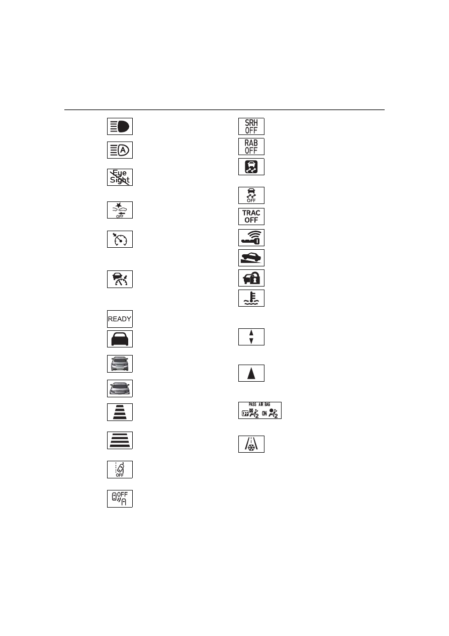
Warning lights and indicators displayed on the instru-
ment cluster
Warning lights
(U.S.A.)
Brake system warning
light
*1
(
(Canada)
Brake system warning
light
*1
(
(red)
High coolant temperature
warning light
*1
(
Charging system warning
light
*1
(
Low engine oil pressure
warning light
*1
(
(U.S.A.)
Malfunction indicator
lamp
*1
(
(Canada)
Malfunction indicator
lamp
*1
(
SRS warning light
*1
(
(U.S.A.)
ABS warning light
*1
(

85
2-1. Instrument cluster
2
Vehicle
s
ta
tu
s information an
d in
dicat
or
s
*1
:These lights turn on when the
engine switch is turned to ON to
indicate that a system check is
being performed. They will turn
off after the engine is started, or
after a few seconds. There may
be a malfunction in a system if a
light does not come on, or turn
off. Have the vehicle inspected
by your Toyota dealer.
*2
:The front passenger’s seat belt
reminder light is located on the
overhead console.
*3
:This light illuminates on the over-
head console.
The indicators inform the driver
of the operating state of the
vehicle’s various systems.
(Canada)
ABS warning light
*1
(
Electric power steering
system warning light
*1
(
Slip indicator
*1
(
Automatic transmission
fluid temperature warning
light (if equipped)
(
Open door warning light
(
Low fuel level warning
light
*1
(
Driver’s and front passen-
ger’s seat belt reminder
light
*1, 2
(
Rear passengers’ seat
belt reminder lights
*1, 3
(
(yellow)
Conventional Cruise Con-
trol indicator (if equipped)
(
BSD/RCTA warning light
(if equipped) (
SRH warning light (if
equipped) (
RAB warning light (if
equipped) (
LED headlight warning
light (
Automatic headlight level-
ing system warning light
(
Master warning light
*1
(
EyeSight warning light (if
equipped) (
Tire pressure warning
light
*1
(
WARNING
■
If a safety system warning
light does not come on
Should a safety system light such
as the ABS and SRS warning light
not come on when you start the
engine, this could mean that
these systems are not available to
help protect you in an accident,
which could result in death or seri-
ous injury. Have the vehicle
inspected by your Toyota dealer
immediately if this occurs.
Indicators
Turn signal indicator
(
Tail light indicator
(
86
2-1. Instrument cluster
Drive mode indicators
Headlight high beam
indicator (
High beam assist indi-
cator (if equipped)
(
EyeSight temporary
stop indicator (if
equipped) (
Pre-Collision Braking
System OFF indica-
tor
*1, 2
(if equipped)
(
(white/green
)
Conventional Cruise
Control indicator (if
equipped) (
(white/green
)
Adaptive Cruise Con-
trol indicator (if
equipped) (
“READY” indicator (if
equipped) (
Lead vehicle indicator
(if equipped) (
Lead vehicle indica-
tor
*3
(if equipped)
(
Your vehicle indicator
(if equipped) (
Following distance set-
ting indicator (if
equipped) (
Following distance set-
ting indicator
*3
(if
equipped) (
Lane Departure Warn-
ing OFF indicator
*1, 2
(if
equipped) (
BSD/RCTA OFF indi-
cator
*2
(if equipped)
(
SRH OFF indicator
*2
(if
equipped) (
RAB OFF indicator
*1, 2
(if equipped) (
(flashes)
Slip indicator
*1
(
VSC OFF indicator
*1, 2
(
TRAC OFF indicator
*1,
2
(
Smart key system indi-
cator
*3
(
Hill-start assist control
ON indicator (
Security indicator
(
(blue)
Low coolant tempera-
ture indicator
*4
Upshift/downshift indi-
cator (vehicles with an
automatic transmis-
sion) (
Shift-up indicator (vehi-
cles with a manual
transmission)
(
Passenger’s fron-
tal airbag ON and
OFF indicator
*1, 5
(
Low outside tempera-
ture indicator
*6
(
P.88)

87
2-1. Instrument cluster
2
Vehicle
statu
s information an
d in
dicator
s
Normal mode
TRACK mode
*1
:These lights turn on when the
engine switch is turned to ON to
indicate that a system check is
being performed. They will turn
off after the engine is started, or
after a few seconds. There may
be a malfunction in a system if a
light does not come on, or turn
off. Have the vehicle inspected
by your Toyota dealer.
*2
:The light comes on when the
system is turned off.
*3
:This light illuminates on the
multi-information display.
*4
:This indicator turns on when the
engine coolant temperature is
low.
*5
:This light illuminates on the over-
head console.
*6
:When the outside temperature is
approximately 37°F (3°C) or
lower, this indicator will illumi-
nate.
Snow mode indicator (if
equipped) (
“SPORT” indicator (if
equipped) (
Snow mode indicator (if
equipped) (
“SPORT” indicator (if
equipped) (
“TRACK” indicator
(
SNOW
SPORT
88
2-1. Instrument cluster
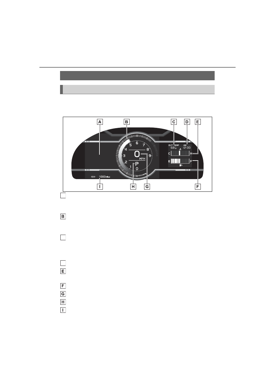
■
Locations of gauges and meters
Normal mode
Multi-information display
Presents the driver with a variety of vehicle data (
Displays warning messages in case of a malfunction (
Tachometer
Displays the engine speed in revolutions per minute
The red zone will be lower than normal, when the engine is cold
Outside temperature
Displays the outside temperature within the range of -40°F (-40°C) to 122°F
(50°C). Low outside temperature indicator comes on when the ambient
temperature is 37°F (3°C) or lower.
Clock
Engine coolant temperature gauge
Displays the engine coolant temperature
Fuel gauge
Speedometer
Shift position and gear position (
Odometer and trip meter display (
Gauges and meters
Meter display
A
C
D

89
2-1. Instrument cluster
2
Vehicle
statu
s information an
d in
dicator
s
TRACK mode
Multi-information display
Presents the driver with a variety of vehicle data (
Displays warning messages in case of a malfunction (
Tachometer
Displays the engine speed in revolutions per minute
The red zone will be lower than normal, when the engine is cold
Outside temperature
Displays the outside temperature within the range of -40°F (-40°C) to 122°F
(50°C). Low outside temperature indicator comes on when the ambient
temperature is 37°F (3°C) or lower.
Clock
Engine coolant temperature gauge
Displays the engine coolant temperature
Fuel gauge
Speedometer
Shift position and gear position (
Odometer and trip meter display (
■
REV indicator
When the engine speed reaches
a set speed, the shift position
and shift range indicator will illu-
minate in orange and a buzzer
will sound. If the engine speed
enters the red zone, the shift
position and shift range indicator
will illuminate in red.
The default setting for the REV indi-
cator is disabled. The setting can
be enabled/disabled on
of the
A
C
D

90
2-1. Instrument cluster
multi-information display. (
The engine speed at which the
REV indicator is displayed can be
changed on
of the multi-infor-
mation display. (
■
Outside temperature display
●
In the following situations, the cor-
rect outside temperature may not
be displayed, or the display may
take longer than normal to
change:
• When stopped, or driving at low
speeds (less than 12 mph [20
km/h])
• When the outside temperature
has changed suddenly (at the
entrance/exit of a garage, tunnel,
etc.)
●
When “--” is displayed, the system
may be malfunctioning.
Take your vehicle to your Toyota
dealer.
■
Liquid crystal display
■
Customization
The meter display can be custom-
ized on the multi-information dis-
play. (
■
Changing the display
Press the display change button
until the desired item is dis-
WARNING
■
The information display at
low temperatures
Allow the interior of the vehicle to
warm up before using the liquid
crystal information display. At
extremely low temperatures, the
information display monitor may
respond slowly, and display
changes may be delayed.
For example, there is a lag
between the driver’s shifting and
the new gear number appearing
on the display. This lag could
cause the driver to downshift
again, causing rapid and exces-
sive engine braking and possibly
an accident resulting in death or
injury.
NOTICE
■
To prevent damage to the
engine and its components
●
Do not let the indicator needle
of the tachometer enter the red
zone, which indicates the maxi-
mum engine speed.
●
Pay extra attention to the
engine speed when the engine
is cold, as the red zone will be
lower than normal.
●
If the engine coolant tempera-
ture gauge indicator is flashing,
the engine may be overheating.
Immediately stop the vehicle in
a safe place, and check the
engine after it has cooled com-
pletely. (
Odometer and trip meter
display

91
2-1. Instrument cluster
2
Vehicle
statu
s information an
d in
dicator
s
played.
■
Display items
Odometer
Displays the total distance the vehi-
cle has been driven.
Trip meter A/Trip meter B
Displays the distance the vehicle
has been driven since the meter
was last reset. Trip meters A and B
can be used to record and display
different distances independently.
To reset, display the desired trip
meter and press and hold the dis-
play change button.
When the headlights or front
position lights are on, the bright-
ness of the meter and instru-
ment panel lights can be
adjusted using the instrument
panel brightness dial.
1
Brighter
2
Darker
■
Instrument panel light bright-
ness adjustment
When the headlights or front posi-
tion lights are turned on, the meter
and instrument panel lights will be
dimmed. However, if the instrument
panel brightness dial is set to the
highest position, the lights will not
dim even if the headlights or front
position are turned on.
■
Auto dimmer cancel
When the surrounding area is
bright, such as during the day, or if
the lights are turned on before nec-
essary, the automatic dimming func-
tion will be cancelled. In this case,
the brightness cannot be adjusted,
even if the instrument panel bright-
ness dial is turned.
■
Customization
Some functions can be customized.
(
The clocks can be adjusted on
the multimedia system screen.
■
Setting the clock to be
adjusted automatically
(vehicles with safety con-
nect)
1
Press
.
Changing the instrument
panel light brightness
Adjusting the clock

92
2-1. Instrument cluster
2
Select
.
3
Select “General”.
4
Select “Clock”.
5
Select “Time Setting”.
6
Select “AUTO”.
The clock will be set automati-
cally where a GPS signal is
available.
■
Setting the clock to be
adjusted automatically
(vehicles without safety
connect)
1
Press
.
2
Select
.
3
Select “General”.
4
Select “Clock”.
5
Select “Time Setting”.
6
Select “Sync With Phone”.
The clock will be set and
adjusted automatically when a
smartphone is connected via
Bluetooth
®
for transferring
phonebook data. For details,
refer to the “MULTIMEDIA
OWNER’S MANUAL”.
■
Adjusting the clock manu-
ally
1
Press
.
2
Select
.
3
Select “General”.
4
Select “Clock”.
5
Select “Time Setting”.
6
Select “Manual” then adjust
the clock.
7
Select “OK”.
■
Changing the clock
between 12H/24H format
1
Press
.
2
Select
.
3
Select “General”.
4
Select “Clock”.
5
Select “12H” or “24H”.
■
Clock settings screen
The clock setting screen can also be
displayed by touching the clock on
the status bar.
Нет комментариевНе стесняйтесь поделиться с нами вашим ценным мнением.
Текст