Toyota Tundra. Manual — part 1972

a
Install the 2 water jacket spacers as shown in the illustration
13
INSTALL CYLINDER HEAD GASKET RH (See INSTALLATION )
14
INSTALL CYLINDER HEAD GASKET LH (See INSTALLATION )
15
INSTALL CYLINDER HEAD SUB-ASSEMBLY RH (See INSTALLATION )
16
INSTALL CYLINDER HEAD SUB-ASSEMBLY LH (See INSTALLATION )
17
INSTALL VALVE STEM CAP
a
Apply a light coat of engine oil to the valve stem caps
b
Install the 32 valve stem caps to the cylinder head
18
INSTALL VALVE LASH ADJUSTER ASSEMBLY
a
Inspect the valve lash adjuster (See INSPECTION )
b
Install the 32 valve lash adjusters to the cylinder head
19
INSTALL NO. 1 VALVE ROCKER ARM SUB-ASSEMBLY
a
Apply engine oil to the lash adjuster tips and valve stem cap ends
b
Install the 32 valve rocker arms as shown in the illustration
NOTE:
Face the cutouts indicated by the arrows in illustration away
from the engine.
Face the "up mark" as shown in the illustration.
Fig. 343: Identifying Up Mark Position For Installing Cylinder
Block Water Jacket Spacer
Courtesy of TOYOTA MOTOR SALES, U.S.A., INC.
NOTE:
Install the lash adjuster at the same place it was removed from.
2009 Toyota Tundra
2009 ENGINE Engine Mechanical (3UR-FBE) - Tundra

Fig. 344: Identifying Valve Rocker Arms Position
Courtesy of TOYOTA MOTOR SALES, U.S.A., INC.
20
INSTALL CAMSHAFT BEARING CAP RH
a
Apply a light coat of engine oil to the camshaft journals, camshaft housings and bearing caps
b
Install the No 1 and No 2 camshafts to the camshaft housing
c
Confirm the marks and numbers on the camshaft bearing caps and place them in their proper
positions and directions
Fig. 345: Identifying Camshaft Bearing Caps Sequence
Courtesy of TOYOTA MOTOR SALES, U.S.A., INC.
d
Temporarily install the 10 bolts in the order shown in the illustration
2009 Toyota Tundra
2009 ENGINE Engine Mechanical (3UR-FBE) - Tundra
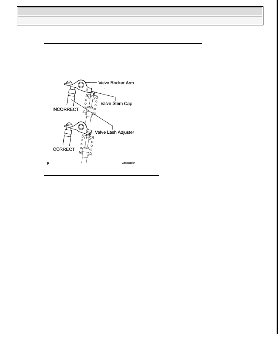
Fig. 346: Identifying Camshaft Bearing Cap Bolts Tightening Order
Courtesy of TOYOTA MOTOR SALES, U.S.A., INC.
21
INSTALL CAMSHAFT HOUSING SUB-ASSEMBLY RH
a
Make sure that the valve rocker arms are installed as shown in the illustration
Fig. 347: Identifying Valve Rocker Arms Position
Courtesy of TOYOTA MOTOR SALES, U.S.A., INC.
b
Apply seal packing in a continuous line as shown in the illustration
Seal packing:
Toyota Genuine Seal Packing Black, Three Bond 1207B or equivalent
Standard seal diameter:
3.5 to 4.0 mm (0.138 to 0.157 in.)
NOTE:
Remove any oil from the contact surface.
Install the camshaft housing within 3 minutes and tighten the
bolts within 15 minutes after applying seal packing.
2009 Toyota Tundra
2009 ENGINE Engine Mechanical (3UR-FBE) - Tundra
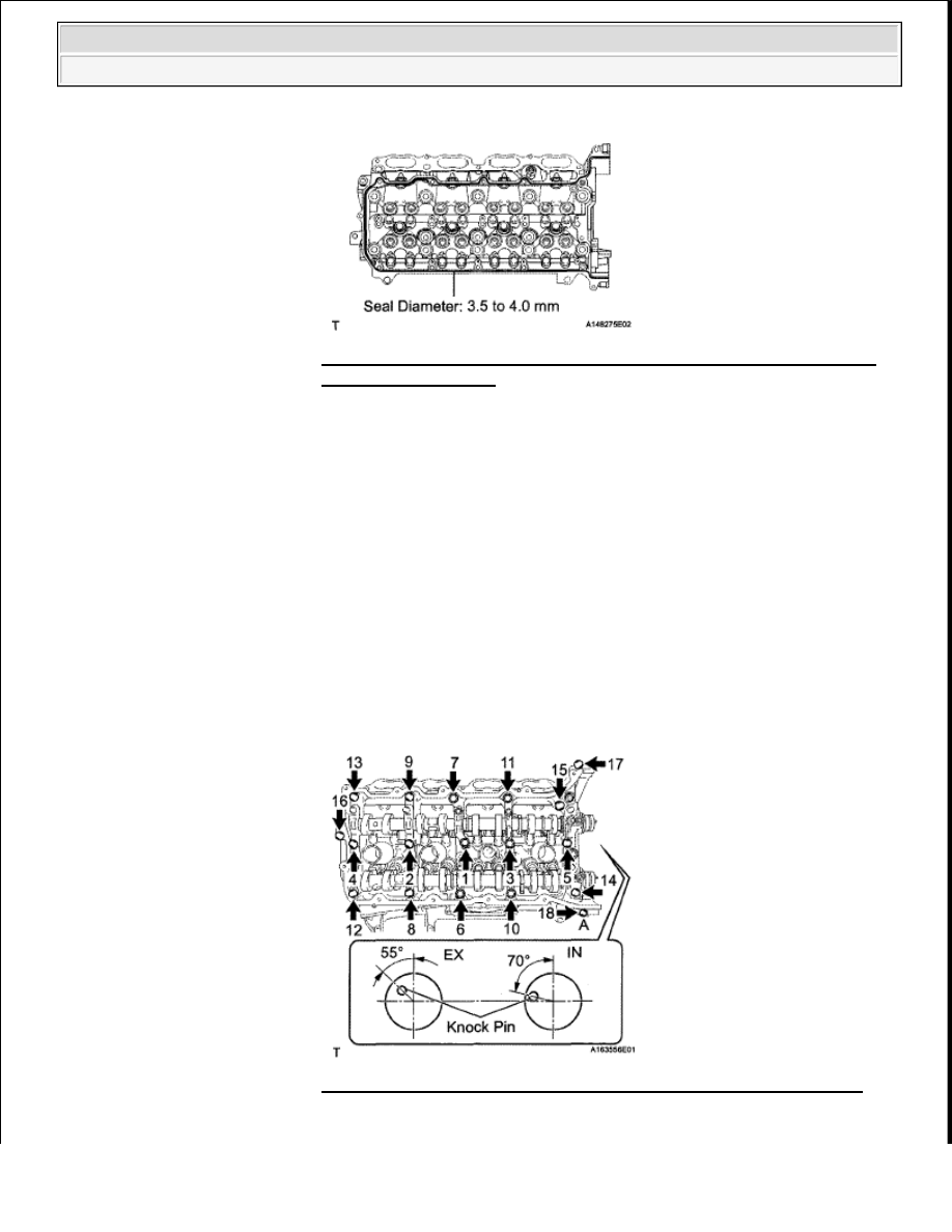
c
Install the camshaft housing, and install the 18 bolts in the order shown in the illustration
Torque: for bolt A
10 N*m (102 kgf*cm, 7 ft.*lbf)
for except bolt A
30 N*m (306 kgf*cm, 22 ft.*lbf)
Fig. 348: Identifying Seal Packing Areas On Camshaft Housing
Sub-Assembly - RH
Courtesy of TOYOTA MOTOR SALES, U.S.A., INC.
NOTE:
Do not start the engine for at least 2 hours after the installation.
Make sure that the knock pin of the camshaft is positioned as
shown in the illustration before installing the camshaft housing.
Fig. 349: Identifying Camshaft Housing Bolts Installing Order
Courtesy of TOYOTA MOTOR SALES, U.S.A., INC.
2009 Toyota Tundra
2009 ENGINE Engine Mechanical (3UR-FBE) - Tundra
Нет комментариевНе стесняйтесь поделиться с нами вашим ценным мнением.
Текст