Toyota Tundra. Manual — part 1308

The wavelength becomes shorter as engine RPM increases.
Fig. 21: Igniter IGT Signal (From ECM To Igniter) & Igniter IGF Signal (From Igniter To
ECM) - Waveform Graph
h. WAVEFORM 7:
Purge VSV
PURGE VSV - WAVEFORM REFERENCE
HINT:
If the waveform is not similar to the illustration, check the waveform again after idling for 10
minutes or more.
Fig. 22: Purge VSV - Waveform Graph
i. WAVEFORM 8:
Item
Content
Terminal No. (Symbols)
Between PRG and E1
Tool Setting
10 V/DIV., 10 to 100 msec./DIV.
Condition
Idling
2008 Toyota Tundra
2008 ENGINE PERFORMANCE Engine Control System (2UZ-FE) - Tundra
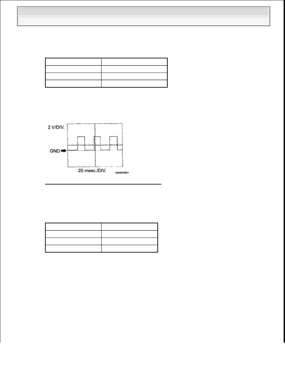
Vehicle speed signal
VEHICLE SPEED SIGNAL - WAVEFORM REFERENCE
HINT:
The wavelength becomes shorter as the vehicle speed increases.
Fig. 23: Vehicle Speed Signal - Waveform Graph
j. WAVEFORM 9:
Throttle actuator positive terminal
THROTTLE ACTUATOR POSITIVE TERMINAL - WAVEFORM REFERENCE
HINT:
The duty ratio varies depending on the throttle actuator operation.
Item
Content
Terminal No. (Symbols)
Between SPD and E1
Tool Setting
2 V/DIV., 20 msec./DIV.
Condition
Driving at 20 km/h (12 mph)
Item
Content
Terminal No. (Symbols) Between M+ and ME01
Tool Setting
5 V/DIV., 1 msec./DIV.
Condition
Idling with warm engine
2008 Toyota Tundra
2008 ENGINE PERFORMANCE Engine Control System (2UZ-FE) - Tundra

Fig. 24: Throttle Actuator Positive Terminal - Waveform Graph
k. WAVEFORM 10:
Throttle actuator negative terminal
THROTTLE ACTUATOR NEGATIVE TERMINAL - WAVEFORM REFERENCE
HINT:
The duty ratio varies depending on the throttle actuator operation.
Fig. 25: Throttle Actuator Negative Terminal - Waveform Graph
l. WAVEFORM 11:
Engine speed signal
ENGINE SPEED SIGNAL - WAVEFORM REFERENCE
Item
Content
Terminal No. (Symbols) Between M- and ME01
Tool Setting
5 V/DIV., 1 msec./DIV.
Condition
Idling with warm engine
Item
Content
Terminal No. (Symbols) Between TACH and E1
Tool Setting
5 V/DIV., 10msec./DIV.
Condition
Idling
2008 Toyota Tundra
2008 ENGINE PERFORMANCE Engine Control System (2UZ-FE) - Tundra
HINT:
The wavelength becomes shorter as the engine RPM increases.
Fig. 26: Engine Speed Signal - Waveform Graph
m. WAVEFORM 12:
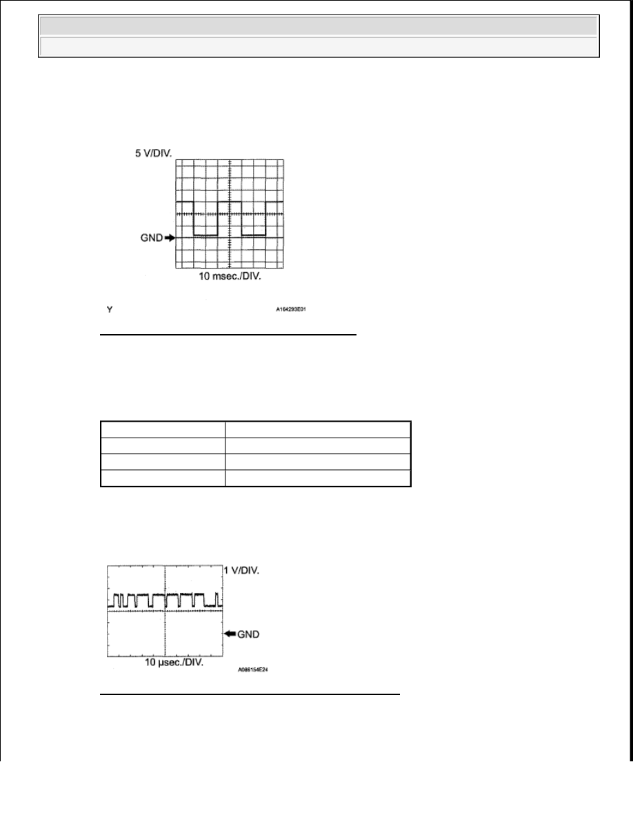
CAN communication signal
CAN COMMUNICATION SIGNAL - WAVEFORM REFERENCE
HINT:
The waveform varies depending on the CAN communication signal.
Fig. 27: CAN Communication Signal - Waveform Graph
n. WAVEFORM 13:
CAN communication signal
Item
Content
Terminal No. (Symbols)
Between CANH and E1
Tool Setting
1 V/DIV., 10 µsec./DIV.
Condition
Engine stops and ignition switch ON
2008 Toyota Tundra
2008 ENGINE PERFORMANCE Engine Control System (2UZ-FE) - Tundra
Нет комментариевНе стесняйтесь поделиться с нами вашим ценным мнением.
Текст