Toyota Tundra. Manual — part 2591

OK: The connectors are properly connected.
NG: CONNECT CONNECTORS PROPERLY
OK: Go to next step
8. CHECK CONNECTORS
a. Disconnect the connectors from the center airbag sensor and the integration control and panel.
b. Check that the connectors (on the center airbag sensor side and integration control and panel side)
are not damaged.
OK: The connectors are not deformed or damaged.
NG: REPLACE INSTRUMENT PANEL WIRE
OK: Go to next step
9. CHECK INSTRUMENT PANEL WIRE (CENTER AIRBAG SENSOR - INTEGRATION
CONTROL AND PANEL)
a. Turn the ignition switch OFF.
b. Disconnect the negative (-) terminal cable from the battery, and wait for at least 90 seconds.
c. Disconnect the connector from the integration control and panel.
d. Using a service wire, connect terminals 23 (PAON) and 17 (P-AB) of connector B.
e. Measure the resistance according to the value(s) in the table below.
Standard Resistance
TESTER CONNECTION SPECIFIED CONDITION TABLE
f. Disconnect the service wire from connector B.
g. Measure the resistance according to the value(s) in the table below.
Standard Resistance
TESTER CONNECTION SPECIFIED CONDITION TABLE
NOTE:
Do not forcibly insert a service wire into the terminals of the
connector when connecting the wire.
Tester Connection
Condition Specified Condition
J37-5 (PAON) - J37-13 (P-AB) Always
Below 1 ohms
Tester Connection
Condition Specified Condition
J37-5 (PAON) - J37-13 (P-AB)
Always
1 Mohms or higher
J37-5 (PAON) - Body ground
2009 Toyota Tundra
2009 RESTRAINTS Supplemental Restraint System - Tundra

h. Connect the negative (-) terminal cable to the battery. and wait for at least 2 seconds.
i. Turn the ignition switch ON.
j. Measure the voltage according to the value(s) in the table below.
Standard voltage
TESTER CONNECTION SPECIFIED CONDITION TABLE
Fig. 118: Identifying Instrument Panel Wire
Courtesy of TOYOTA MOTOR SALES, U.S.A., INC.
NG: REPLACE INSTRUMENT PANEL WIRE
OK: Go to next step
10. CHECK PASSENGER AIRBAG ON/OFF INDICATOR (SOURCE VOLTAGE)
a. Connect the connectors to the center airbag sensor.
b. Connect the negative (-) terminal cable to the battery, and wait for at least 2 seconds.
c. Turn the ignition switch ON.
d. Measure the voltage according to the value(s) in the table below.
Standard voltage
TESTER CONNECTION SPECIFIED CONDITION TABLE
J37-13 (P-AB) - Body ground
Tester Connection
Switch Condition Specified Condition
J37-5 (PAON) - Body ground
Ignition switch ON
Below 1 V
J37-13 (P-AB) - Body ground
Tester Connection
Switch Condition Specified Condition
J37-16 (IG+) - Body ground Ignition switch ON
11 to 14 V
2009 Toyota Tundra
2009 RESTRAINTS Supplemental Restraint System - Tundra
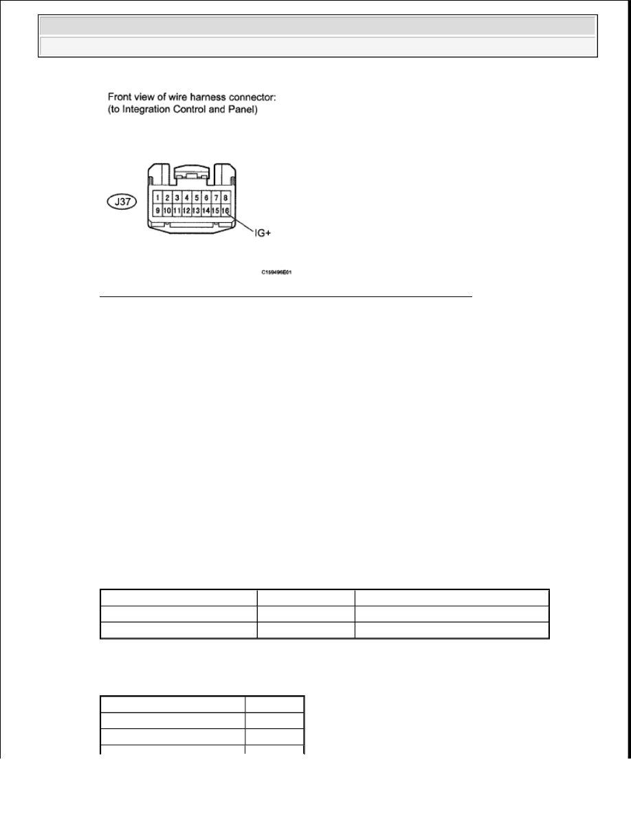
Fig. 119: Identifying Integration Control & Panel Connector Terminal
Courtesy of TOYOTA MOTOR SALES, U.S.A., INC.
NG: REPLACE HARNESS AND CONNECTOR (PASSENGER AIRBAG ON/OFF INDICATOR
- BATTERY) OR BATTERY
OK: Go to next step
11. CHECK PASSENGER AIRBAG ON/OFF INDICATOR
a. Turn the ignition switch OFF.
b. Disconnect the negative (-) terminal cable from the battery, and wait for at least 90 seconds.
c. Connect the connector to the integration control and panel.
d. Disconnect the connectors from the center airbag sensor.
e. Connect the negative (-) terminal cable to the battery, and wait for at least 2 seconds.
f. Turn the ignition switch ON.
g. Check the indicator according to the value(s) in the table below.
Result
RESULT TABLE
Result
RESULT TABLE
Connection
Switch Condition Passenger airbag ON/OFF indicator
J46-23 (PAON) - Body ground Ignition switch ON
"ON" comes on
J46-17 (P-AB) - Body ground Ignition switch ON
"OFF" comes on
Result
Proceed to
NG (for Column Shift Type)
A
NG (for Floor Shift Type)
B
2009 Toyota Tundra
2009 RESTRAINTS Supplemental Restraint System - Tundra
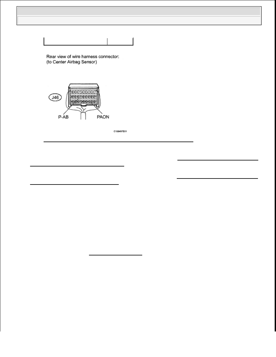
Fig. 120: Identifying Center Airbag Sensor Connector Terminals
Courtesy of TOYOTA MOTOR SALES, U.S.A., INC.
A: REPLACE INTEGRATION CONTROL AND PANEL (See INTEGRATION CONTROL AND
PANEL (FOR COLUMN SHIFT TYPE) ). )
B: REPLACE INTEGRATION CONTROL AND PANEL (See INTEGRATION CONTROL AND
PANEL (FOR FLOOR SHIFT TYPE) )
C: Go to next step
12. CHECK CENTER AIRBAG SENSOR
a. Turn the ignition switch OFF.
b. Disconnect the negative (-) terminal cable from the battery, and wait for at least 90 seconds.
c. Connect the connectors to the center airbag sensor.
d. Connect the negative (-) terminal cable to the battery and wait for at least 2 seconds.
e. Turn the ignition switch ON, and wait for at least 60 seconds.
f. Clear the DTCs (see DTC CHECK/CLEAR ).
g. Turn the ignition switch OFF.
h. Turn the ignition switch ON, and wait for at least 60 seconds.
OK
C
2009 Toyota Tundra
2009 RESTRAINTS Supplemental Restraint System - Tundra
Нет комментариевНе стесняйтесь поделиться с нами вашим ценным мнением.
Текст