Toyota Tundra. Manual — part 251

Fig. 386: Locating Speaker Assembly Bolts (RH)
Courtesy of TOYOTA MOTOR SALES, U.S.A., INC.
a. Remove the 2 bolts.
b. Remove the speaker and disconnect the connector.
8. REMOVE NO. 3 INSTRUMENT PANEL SPEAKER PANEL SUB-ASSEMBLY
a. Using a screwdriver, detach the 6 clips and 2 claws.
HINT:
Tape the screwdriver tip before use.
b. Remove the speaker panel.
Fig. 387: Identifying No 3 Instrument Panel Speaker Panel Clips And Claws
Courtesy of TOYOTA MOTOR SALES, U.S.A., INC.
NOTE:
Do not touch the cone part of the speaker.
2009 Toyota Tundra
2009 ACCESSORIES AND EQUIPMENT Audio/Visual - Tundra

9. REMOVE FRONT NO. 4 SPEAKER ASSEMBLY (for 12 Speakers)
a. Remove the 2 bolts.
b. Remove the speaker and disconnect the connector.
Fig. 388: Locating Front No 4 Speaker Assembly Bolts (For 12 Speakers)
Courtesy of TOYOTA MOTOR SALES, U.S.A., INC.
INSPECTION
1. INSPECT FRONT NO. 2 SPEAKER ASSEMBLY (for Standard)
a. Measure the resistance according to the value(s) in the table below.
Standard resistance
TESTER CONNECTION SPECIFIED CONDITION
Fig. 389: Identifying Speaker Assembly Connector Terminals (For Standard)
Courtesy of TOYOTA MOTOR SALES, U.S.A., INC.
NOTE:
Do not touch the cone part of the speaker.
Tester Connection Condition Specified Condition
1 -3
Always
Below 1 ohms
2-4
3-4
Always
3.6 to 4.4 ohms
2009 Toyota Tundra
2009 ACCESSORIES AND EQUIPMENT Audio/Visual - Tundra
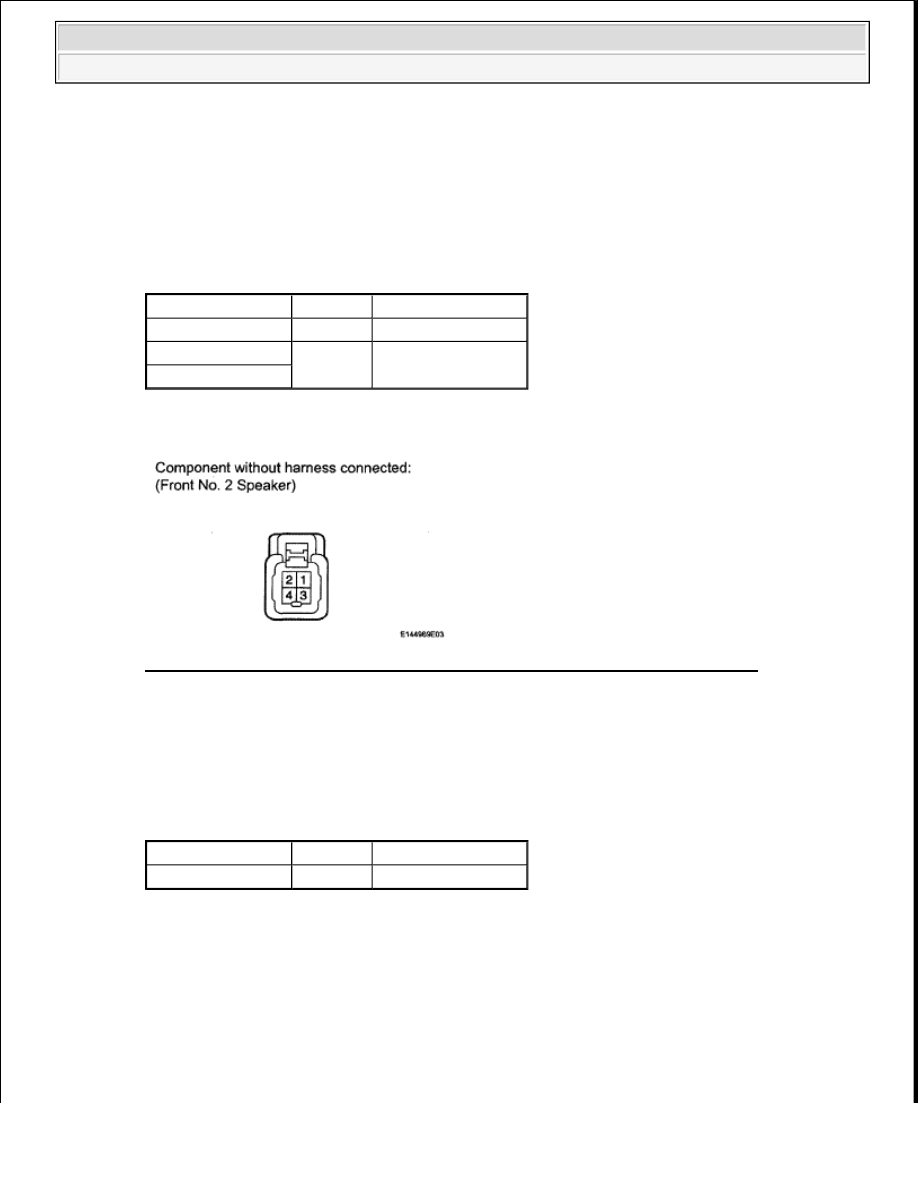
If the result is not as specified, replace the speaker assembly.
2. INSPECT FRONT NO. 2 SPEAKER ASSEMBLY (for 12 Speakers)
a. Measure the resistance according to the value(s) in the table below.
Standard resistance
TESTER CONNECTION SPECIFIED CONDITION
If the result is not as specified, replace the speaker assembly.
Fig. 390: Identifying Speaker Assembly Connector Terminals (For 12 Speakers)
Courtesy of TOYOTA MOTOR SALES, U.S.A., INC.
3. INSPECT FRONT NO. 4 SPEAKER ASSEMBLY (for 12 Speakers)
a. Measure the resistance according to the value(s) in the table below.
Standard resistance
TESTER CONNECTION SPECIFIED CONDITION
If the result is not as specified, replace the speaker assembly.
Tester Connection Condition Specified Condition
3-4
Always
1.3 to 2.3 ohms
3-1
Always
Below 1 ohms
4-2
Tester Connection Condition Specified Condition
1-2
Always
1.5 to 2.1 ohms
2009 Toyota Tundra
2009 ACCESSORIES AND EQUIPMENT Audio/Visual - Tundra

Fig. 391: Identifying Front No 4 Speaker Assembly Connector Terminals (For 12 Speakers)
Courtesy of TOYOTA MOTOR SALES, U.S.A., INC.
INSTALLATION
1. INSTALL FRONT NO. 4 SPEAKER ASSEMBLY (for 12 Speakers)
a. Connect the connector.
b. Temporarily install the speaker by aligning the positioning pins of the speaker with the instrument
panel.
c. Install the speaker with the 2 bolts.
2. INSTALL NO. 3 INSTRUMENT PANEL SPEAKER PANEL SUB-ASSEMBLY
a. Attach the 6 clips and 2 claws to install the speaker panel.
NOTE:
Do not touch the cone part of the speaker.
When installing the speaker to the instrument panel, be careful
that the wires do not get caught between the parts.
Fig. 392: Locating Front No 4 Speaker Assembly Bolts (For 12
Speakers)
Courtesy of TOYOTA MOTOR SALES, U.S.A., INC.
2009 Toyota Tundra
2009 ACCESSORIES AND EQUIPMENT Audio/Visual - Tundra
Нет комментариевНе стесняйтесь поделиться с нами вашим ценным мнением.
Текст