Toyota Tundra. Manual — part 2585

Fig. 96: Identifying No. 2 Floor Wire
Courtesy of TOYOTA MOTOR SALES, U.S.A., INC.
NG: REPLACE NO. 2 FLOOR WIRE
OK: REPLACE FRONT SEAT WIRE RH
8. CHECK FOR DTC (CENTER AIRBAG SENSOR)
a. Turn the ignition switch ON, and wait for at least 60 seconds.
b. Clear the DTCs (see DTC CHECK/CLEAR ).
c. Turn the ignition switch OFF.
d. Turn the ignition switch ON, and wait for at least 60 seconds.
e. Check for DTCs (see DTC CHECK/CLEAR ).
OK: DTC B1650 is not output.
HINT:
Codes other than DTC B1650 maybe output at this time, but they are not related to this check.
Fig. 97: Identifying Center Airbag Sensor
Courtesy of TOYOTA MOTOR SALES, U.S.A., INC.
NG: Go to step 9
OK: USE SIMULATION METHOD TO CHECK (See DIAGNOSIS SYSTEM )
9. CHECK CONNECTION OF CONNECTORS
a. Turn the ignition switch OFF.
b. Disconnect the negative (-) terminal cable from the battery, and wait for at least 90 seconds.
c. Check that the connectors are properly connected to the center airbag sensor and the occupant
classification ECU.
OK: The connectors are properly connected.
NG: CONNECT CONNECTORS PROPERLY
2009 Toyota Tundra
2009 RESTRAINTS Supplemental Restraint System - Tundra
OK: Go to next step
10. CHECK CONNECTORS
a. Disconnect the connectors from the center airbag sensor and the occupant classification ECU.
b. Check that the connectors (on the center airbag sensor side and occupant classification ECU side)
are not damaged.
OK: The connectors are not damaged or damaged.
NG: REPLACE HARNESS AND CONNECTOR
OK: Go to next step
11. CHECK NO. 2 FLOOR WIRE (CENTER AIRBAG SENSOR - OCCUPANT CLASSIFICATION
ECU)
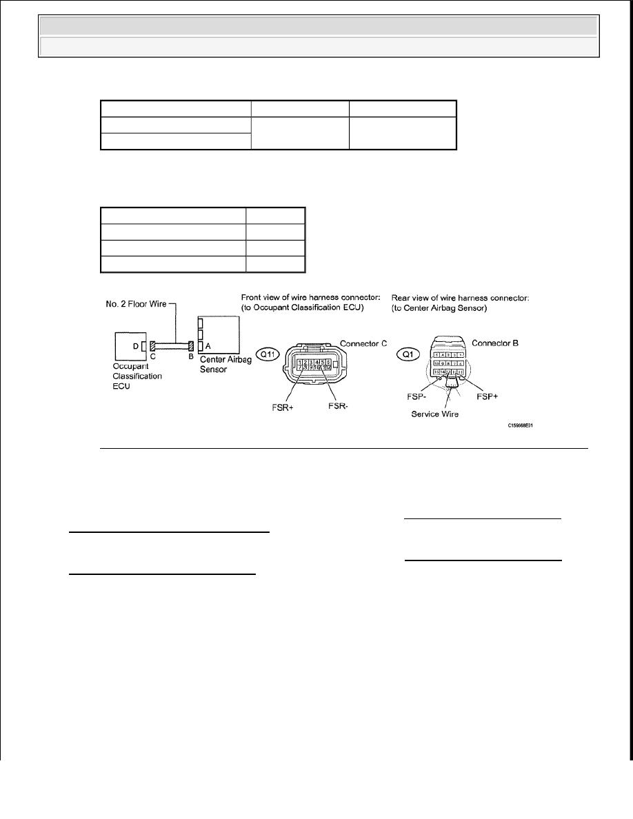
a. Using a service wire, connect terminal 12 (FSP+) and 13 (FSP-) of connector B.
b. Measure the resistance according to the value(s) in the table below.
Standard Resistance
TESTER CONNECTION SPECIFIED CONDITION TABLE
c. Disconnect the service wire from connector B.
d. Measure the resistance according to the value(s) in the table below.
Standard Resistance
TESTER CONNECTION SPECIFIED CONDITION TABLE
e. Connect the negative (-) terminal cable to the battery, and wait for at least 2 seconds.
f. Turn the ignition switch ON.
g. Measure the voltage according to the value(s) in the table below.
Standard voltage
NOTE:
Do not forcibly insert a service wire into the terminals of the
connector when connecting the wire.
Tester Connection
Condition Specified Condition
Q11-4 (FSR-) - Q11-8 (FSR+) Always
Below 1 ohms
Tester Connection
Condition Specified Condition
Q11-4 (FSR-) - Q11-8 (FSR+)
Always
1 Mohms or higher
Q11-4 (FSR-) - Body ground
Q11-8 (FSR+) - Body ground
2009 Toyota Tundra
2009 RESTRAINTS Supplemental Restraint System - Tundra
TESTER CONNECTION SPECIFIED CONDITION TABLE
Result
RESULT TABLE
Fig. 98: Identifying No. 2 Floor Wire (Center Airbag Sensor - Occupant Classification ECU)
Courtesy of TOYOTA MOTOR SALES, U.S.A., INC.
A: REPLACE NO. 2 FLOOR WIRE
B: REPLACE CENTER AIRBAG SENSOR ASSEMBLY (See CENTER AIRBAG SENSOR
ASSEMBLY (for Column Shift Type) )
C: REPLACE CENTER AIRBAG SENSOR ASSEMBLY (See CENTER AIRBAG SENSOR
ASSEMBLY (for Floor Shift Type) )
DTC B1651/33: MANUAL CUT OFF SWITCH TROUBLE
DESCRIPTION
The manual cut off switch circuit consists of the center airbag sensor and the airbag cut-off switch cylinder.
The front passenger airbag can be optionally deactivated via this circuit by turning the manual cut-off switch to
the OFF position.
If the front passenger airbag is deactivated, the passenger airbag OFF indicator comes on to inform the
passengers.
Tester Connection
Switch Condition Specified Condition
Q11-4 (FSR-) - Body ground
Ignition switch ON
Below 1 V
Q11-8 (FSR+) - Body ground
Result
Proceed to
NG
A
OK (for Column Shift Type)
B
OK (for Floor Shift Type)
C
2009 Toyota Tundra
2009 RESTRAINTS Supplemental Restraint System - Tundra

DTC B1651/33 is recorded when a malfunction is detected in the manual cut-off switch circuit.
DTC TROUBLE DETECTION CONDITION TABLE
WIRING DIAGRAM
Fig. 99: Identifying Manual Cut Off Switch Trouble - Wiring Diagram
Courtesy of TOYOTA MOTOR SALES, U.S.A., INC.
INSPECTION PROCEDURE
DTC
Code
Detection Condition
Trouble Area
B1651/33
When all conditions below are met:
The center airbag sensor receives a line short circuit signal, an
open circuit signal, a short circuit to ground signal or a short
circuit to B+ signal in the manual cut off switch circuit for 2
seconds.
Manual cut off switch malfunction
Center airbag sensor malfunction
Instrument
panel wire
Airbag cut-off
switch cylinder
Center airbag
sensor assembly
NOTE:
When disconnecting the cable from the negative (-) battery terminal while
performing repairs, some systems need to be initialized after the cable is
reconnected (see INITIALIZATION ).
2009 Toyota Tundra
2009 RESTRAINTS Supplemental Restraint System - Tundra
Нет комментариевНе стесняйтесь поделиться с нами вашим ценным мнением.
Текст