Toyota Tundra. Manual — part 2844

Fig. 122: Identifying J25 Transmission Control Switch Connector Terminals
Courtesy of TOYOTA MOTOR SALES, U.S.A., INC.
b. for Floor Shift Type:
1. Disconnect the J24 transmission control switch connector.
2. Measure the resistance according to the value (s) in the table below.
Standard resistance
TESTER CONNECTION SPECIFIED CONDITION TABLE
Tester Connection
Condition
Specified Condition
3 (IG) - 7 (S)
Shift lever position on S, "+" or "-"
Below 1 ohms
2 (SFTU) - 5 (E)
Shift lever held in "+" (Up-shift)
Below 1 ohms
1 (SFTD) - 5 (E)
Shift lever held in "-" (Down-shift)
Below 1 ohms
3 (IG) - 7 (S)
Shift lever position not on S, "+" or "-" 10 kohms or higher
2 (SFTU) - 5 (E)
Shift lever position on S
10 kohms or higher
1 (SFTD) - 5 (E)
Shift lever position on S
10 kohms or higher
2009 Toyota Tundra
2009 TRANSMISSION AB60F Automatic Transaxle - Tundra
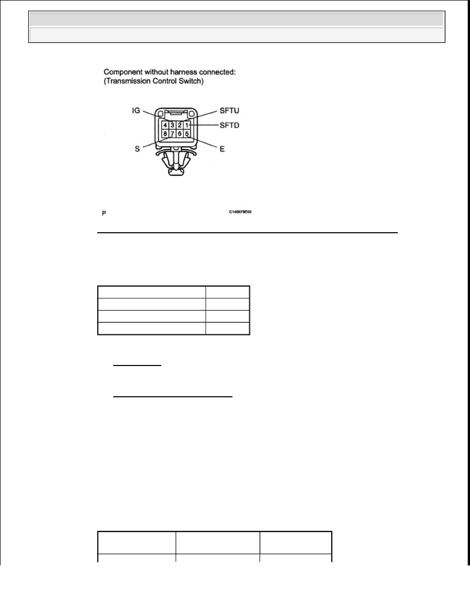
Fig. 123: Identifying J24 Transmission Control Switch Connector Terminals
Courtesy of TOYOTA MOTOR SALES, U.S.A., INC.
Result
RESULT REFERENCE TABLE
B: REPLACE COLUMN SHIFT LEVER SUB-ASSEMBLY (TRANSMISSION CONTROL
SWITCH) (See REMOVAL )
C: REPLACE TRANSMISSION FLOOR SHIFT ASSEMBLY (TRANSMISSION CONTROL
SWITCH) (See ON-VEHICLE INSPECTION )
A: Go to next step.
2. CHECK HARNESS AND CONNECTOR (TRANSMISSION CONTROL SWITCH - BATTERY,
BODY GROUND)
a. for Column Shift Type:
1. Disconnect the J25 transmission control switch connector.
2. Measure the voltage according to the value (s) in the table below.
Standard voltage
TESTER CONNECTION SPECIFIED CONDITION TABLE
Result
Proceed to
OK
A
NG (for Column Shift Type)
B
NG (for Floor Shift Type)
C
Tester Connection
Switch Condition
Specified
Condition
2009 Toyota Tundra
2009 TRANSMISSION AB60F Automatic Transaxle - Tundra
3. Measure the resistance according to the value (s) in the table below.
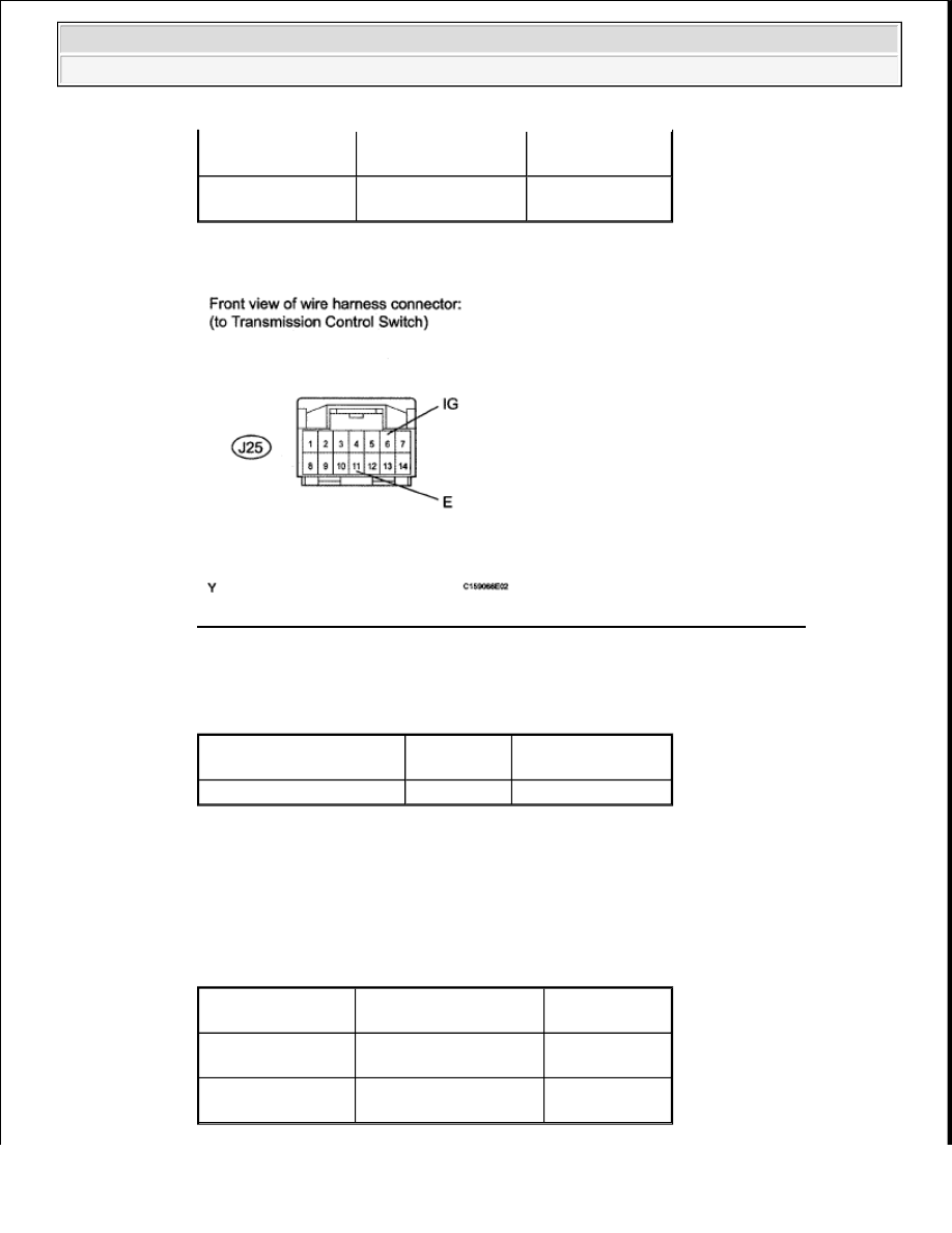
Fig. 124: Identifying J25 Transmission Control Switch Connector Terminals
Courtesy of TOYOTA MOTOR SALES, U.S.A., INC.
Standard resistance
TESTER CONNECTION SPECIFIED CONDITION TABLE
b. for Floor Shift Type:
1. Disconnect the J24 transmission control switch connector.
2. Measure the voltage according to the value (s) in the table below.
Standard voltage
TESTER CONNECTION SPECIFIED CONDITION TABLE
J25-6 (IG) - Body
ground
Ignition switch ON
11 to 14 V
J25-6 (IG) - Body
ground
Ignition switch off
Below 1 V
Tester Connection
Condition
Specified
Condition
J25-11 (E) - Body ground
Always
Below 1 ohms
Tester Connection
Switch Condition
Specified
Condition
J24-3 (IG) - Body
ground
Ignition switch ON
11 to 14 V
J24-3 (IG) - Body
ground
Ignition switch off
Below 1 V
2009 Toyota Tundra
2009 TRANSMISSION AB60F Automatic Transaxle - Tundra

3. Measure the resistance according to the value (s) in the table below.
Standard resistance
TESTER CONNECTION SPECIFIED CONDITION TABLE
Fig. 125: Identifying J24 Transmission Control Switch Connector Terminals
Courtesy of TOYOTA MOTOR SALES, U.S.A., INC.
NG: REPAIR OR REPLACE HARNESS OR CONNECTOR
OK: Go to next step.
3. CHECK HARNESS AND CONNECTOR (TRANSMISSION CONTROL SWITCH - ECM)
a. Disconnect the A24 ECM connector.
b. Measure the voltage according to the value (s) in the table below.
Standard voltage
TESTER CONNECTION SPECIFIED CONDITION TABLE
Tester Connection
Condition
Specified
Condition
J24-5 (E) - Body ground
Always
Below 1 ohms
Tester Connection
Condition
Specified Condition
A24-25 (S) - Body ground
Ignition switch ON
Shift lever position on S, "+" or "-"
11 to 14 V
A24-25 (S) - Body ground
Ignition switch ON
Shift lever position not on S, "+" or "-"
Below 1 V
2009 Toyota Tundra
2009 TRANSMISSION AB60F Automatic Transaxle - Tundra
Нет комментариевНе стесняйтесь поделиться с нами вашим ценным мнением.
Текст