Toyota Tundra. Manual — part 2737
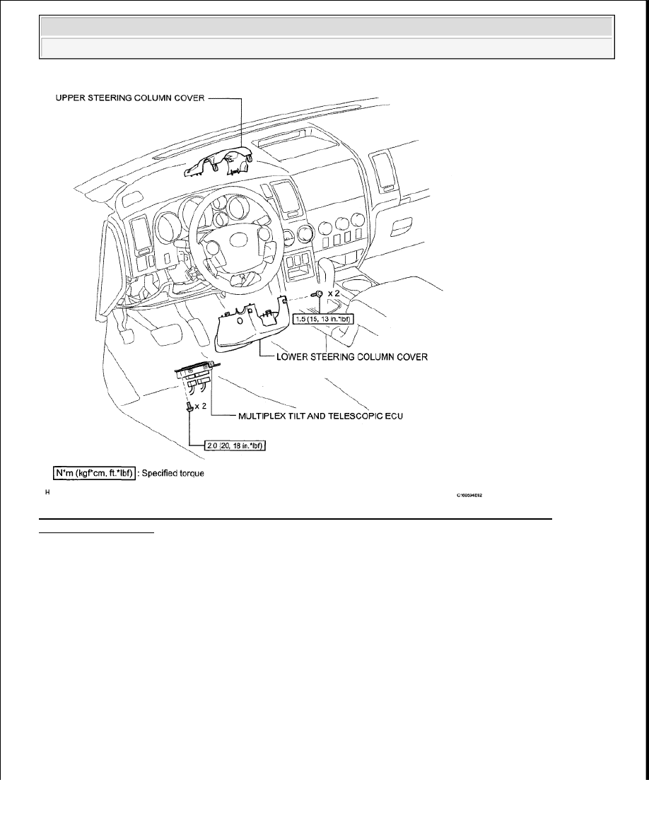
Fig. 186: Identifying Multiplex Tilt & Telescopic ECU Replacement Components With Torque
Specification (2 Of 2)
Courtesy of TOYOTA MOTOR SALES, U.S.A., INC.
REMOVAL
1. DISCONNECT CABLE FROM NEGATIVE BATTERY TERMINAL
CAUTION: Wait at least 90 seconds after disconnecting the cable from the
negative (-) battery terminal to prevent airbag and seat belt
pretensioner activation.
NOTE:
After the ignition switch is turned OFF, the navigation system
requires approximately 90 seconds to record various types of
memory and settings. As a result, after turning the ignition switch
OFF, wait 90 seconds or more before disconnecting the cable from
the negative (-) battery terminal.
2009 Toyota Tundra
2009 STEERING Steering Column - Tundra

2. REMOVE UPPER STEERING COLUMN COVER
a. Remove the 2 screws.
HINT:
Turn the steering wheel to the right and left as necessary to remove the 2 screws.
Fig. 187: Removing/Installing Upper Steering Column Cover Screws
Courtesy of TOYOTA MOTOR SALES, U.S.A., INC.
b. Detach the 4 clips.
c. Detach the claw to remove the upper steering column cover.
Fig. 188: Identifying Upper Steering Column Cover Clips
Courtesy of TOYOTA MOTOR SALES, U.S.A., INC.
3. REMOVE LOWER STEERING COLUMN COVER
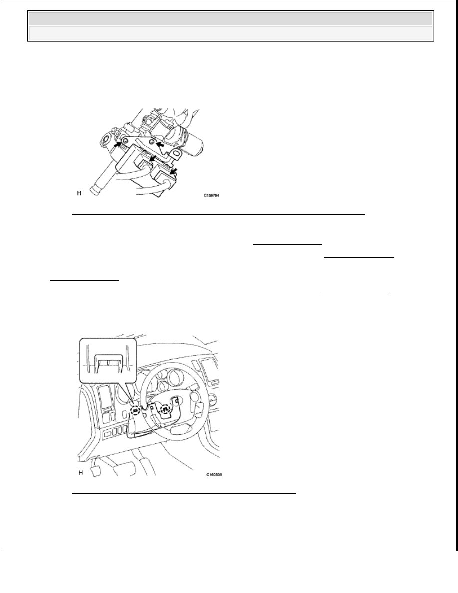
a. Detach the 2 claws to remove the lower steering column cover.
Some systems need to be initialized after the cable is reconnected
(see INITIALIZATION ).
2009 Toyota Tundra
2009 STEERING Steering Column - Tundra

Fig. 189: Locating Lower Steering Column Cover Claws
Courtesy of TOYOTA MOTOR SALES, U.S.A., INC.
4. REMOVE HOOD LOCK CONTROL LEVER SUB-ASSEMBLY (See REMOVAL )
5. REMOVE LOWER INSTRUMENT PANEL FINISH PANEL SUB-ASSEMBLY LH (See
REMOVAL )
6. REMOVE NO. 1 INSTRUMENT PANEL SAFETY PAD INSERT (See REMOVAL )
7. REMOVE NO. 1 AIR DUCT SUB-ASSEMBLY (See REMOVAL )
8. REMOVE MULTIPLEX TILT AND TELESCOPIC ECU
a. Disconnect the 2 ECU connectors.
b. Remove the 2 screws and ECU.
Fig. 190: Locating Multiplex Tilt And Telescopic ECU Connectors & Screws
Courtesy of TOYOTA MOTOR SALES, U.S.A., INC.
INSTALLATION
1. INSTALL MULTIPLEX TILT AND TELESCOPIC ECU
a. Install the ECU with the 2 screws.
2009 Toyota Tundra
2009 STEERING Steering Column - Tundra
Torque: 1.5 N*m (15 kgf*cm, 13 in.*lbf)
b. Connect the 2 ECU connectors.
Fig. 191: Locating Multiplex Tilt And Telescopic ECU Connectors & Screws
Courtesy of TOYOTA MOTOR SALES, U.S.A., INC.
2. INSTALL NO. 1 AIR DUCT SUB-ASSEMBLY (See INSTALLATION )
3. INSTALL NO. 1 INSTRUMENT PANEL SAFETY PAD INSERT (See INSTALLATION )
4. INSTALL LOWER INSTRUMENT PANEL FINISH PANEL SUB-ASSEMBLY LH (See
INSTALLATION )
5. INSTALL HOOD LOCK CONTROL LEVER SUB-ASSEMBLY (See INSTALLATION )
6. INSTALL LOWER STEERING COLUMN COVER
a. Attach the 2 claws to install the steering column lower cover.
Fig. 192: Identifying Lower Steering Column Cover Claws
Courtesy of TOYOTA MOTOR SALES, U.S.A., INC.
7. INSTALL UPPER STEERING COLUMN COVER
a. Attach the claw to install the upper steering column cover.
2009 Toyota Tundra
2009 STEERING Steering Column - Tundra
Нет комментариевНе стесняйтесь поделиться с нами вашим ценным мнением.
Текст