Toyota Tundra. Manual — part 285

Fig. 66: Identifying ECM Communication Stop Mode - Wiring Diagram (2 Of 2)
Courtesy of TOYOTA MOTOR SALES, U.S.A., INC.
INSPECTION PROCEDURE
HINT:
Operating the ignition switch, any switches or any doors triggers related ECU and sensor communication with
the CAN, which causes resistance variation.
1. CHECK HARNESS AND CONNECTOR (ECM - BATTERY AND BODY GROUND)
a. Disconnect the A24 and D74 ECM connectors.
b. Measure the resistance according to the value(s) in the table below.
Standard resistance
STANDARD RESISTANCE SPECIFICATION TABLE
2009 Toyota Tundra
2009 ACCESSORIES & EQUIPMENT CAN Communication - Tundra

c. Measure the voltage according to the value(s) in the table below.
Standard voltage
STANDARD VOLTAGE SPECIFICATION TABLE
Fig. 67: Identifying A24 And D74 ECM Connector Terminals
Courtesy of TOYOTA MOTOR SALES, U.S.A., INC.
Tester Connection
Condition Specified Condition
D74-81 (E1) - Body ground
Always
Below 1 ohms
D74-42 (E02) - Body ground
D74-43 (E01) - Body ground
D74-82 (ME01) - Body ground
Tester Connection
Condition
Specified
Condition
A24-1 (BATT) - Body
ground
Always
11 to 14 V
A24-2 (+B2) - Body
ground
When battery's positive (+) voltage is applied to
terminal MREL
A24-3 (+B) - Body ground
When battery's positive (+) voltage is applied to
terminal MREL
A24-34 (MREL) - Body
ground
Ignition switch OFF
2009 Toyota Tundra
2009 ACCESSORIES & EQUIPMENT CAN Communication - Tundra
Result
RESULT REFERENCE TABLE
B: REPLACE ECM (See REMOVAL )
C: REPLACE ECM (See REMOVAL )
D: REPAIR OR REPLACE HARNESS OR CONNECTOR
A: REPLACE ECM (See REMOVAL )
MAIN BODY ECU COMMUNICATION STOP MODE
DESCRIPTION
SYMPTOM TABLE
WIRING DIAGRAM
Result
Proceed to
OK (for 1GR-FE)
A
OK (for 2UZ-FE)
B
OK (for 3UR-FE)
C
NG
D
Detection Item
Symptom
Trouble Area
MAIN BODY ECU
COMMUNICATION STOP
MODE
When either condition below is met:
Main Body is not displayed on "CAN Bus
Check".
Applies to "MAIN BODY ECU
COMMUNICATION STOP MODE" in
"DTC COMBINATION TABLE".
Power source or
inside main body
ECU
Main body ECU
branch wire or
connector (V Bus)
Main body ECU
2009 Toyota Tundra
2009 ACCESSORIES & EQUIPMENT CAN Communication - Tundra
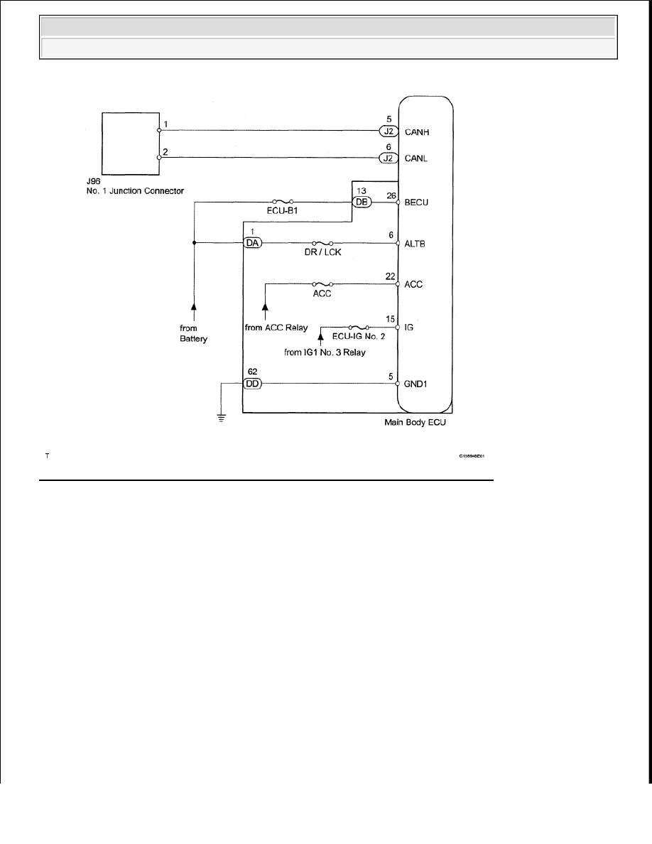
Fig. 68: Identifying Main Body ECU Communication Stop Mode - Wiring Diagram
Courtesy of TOYOTA MOTOR SALES, U.S.A., INC.
INSPECTION PROCEDURE
HINT:
Operating the ignition switch, any switches or any doors triggers related ECU and sensor communication with
the CAN, which causes resistance variation.
1. DISCONNECT CABLE FROM NEGATIVE BATTERY TERMINAL
a. Disconnect the cable from the negative (-) battery terminal before measuring the resistances of the
main wire and the branch wire.
CAUTION: Wait at least 90 seconds after disconnecting the cable from the
negative (-) battery terminal to prevent airbag and seat belt
pretensioner activation.
NOTE:
After the ignition switch is turned OFF, the navigation system
requires approximately 90 seconds to record various types of
2009 Toyota Tundra
2009 ACCESSORIES & EQUIPMENT CAN Communication - Tundra
Нет комментариевНе стесняйтесь поделиться с нами вашим ценным мнением.
Текст