Toyota Tundra. Manual — part 1088
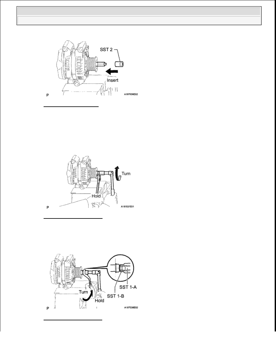
Fig. 12: Inserting SST 2
Courtesy of TOYOTA MOTOR SALES, U.S.A., INC.
d. To loosen the pulley nut, turn SST 1-A in the direction shown in the illustration.
Fig. 13: Turning SST 1-A
Courtesy of TOYOTA MOTOR SALES, U.S.A., INC.
e. Remove the generator from SST 2.
f. Turn SST 1-B, and remove SST 1-A and B.
Fig. 14: Turning SST 1-B
Courtesy of TOYOTA MOTOR SALES, U.S.A., INC.
NOTE:
To prevent damage to the rotor shaft, do not loosen the pulley nut
more than one-half turn.
2009 Toyota Tundra
2009 ELECTRICAL Charging (3UR-FBE) - Tundra
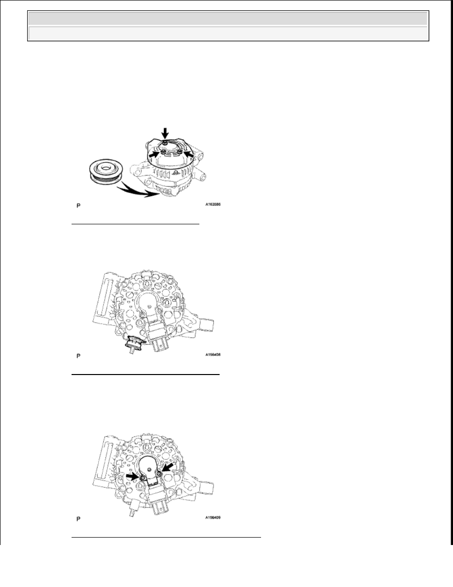
g. Remove the pulley nut and pulley.
2. REMOVE GENERATOR REAR END COVER
a. Place the generator on the pulley.
b. Remove the 3 nuts and end cover.
Fig. 15: Locating End Cover Nuts
Courtesy of TOYOTA MOTOR SALES, U.S.A., INC.
c. Remove the terminal insulator.
Fig. 16: Identifying Terminal Insulator
Courtesy of TOYOTA MOTOR SALES, U.S.A., INC.
3. REMOVE GENERATOR BRUSH HOLDER ASSEMBLY
a. Remove the 2 screws and brush holder.
Fig. 17: Locating Generator Brush Holder Screws
2009 Toyota Tundra
2009 ELECTRICAL Charging (3UR-FBE) - Tundra

Courtesy of TOYOTA MOTOR SALES, U.S.A., INC.
4. REMOVE GENERATOR COIL ASSEMBLY
a. Remove the 4 bolts.
Fig. 18: Locating Generator Coil Bolts
Courtesy of TOYOTA MOTOR SALES, U.S.A., INC.
b. Using SST, remove the coil assembly.
SST 09950-40011 (09951-04020,09952-04010, 09953-04020, 09954-04010, 09955-04071, 09957-
04010, 09958-04011)
Fig. 19: Removing Coil Assembly Using SST
Courtesy of TOYOTA MOTOR SALES, U.S.A., INC.
c. Remove the generator washer.
5. REMOVE GENERATOR ROTOR ASSEMBLY
INSPECTION
1. INSPECT GENERATOR ROTOR ASSEMBLY
a. Check the rotor for an open circuit.
1. Measure the resistance according to the value(s) in the table below.
Standard Resistance
2009 Toyota Tundra
2009 ELECTRICAL Charging (3UR-FBE) - Tundra

100 A Type and 130 A Type
RESISTANCE SPECIFIED CONDITION
Fig. 20: Measuring Resistance Between Slip Rings
Courtesy of TOYOTA MOTOR SALES, U.S.A., INC.
150 A Type
RESISTANCE SPECIFIED CONDITION
If the result is not as specified, replace the rotor assembly.
b. Check if the rotor is grounded.
1. Measure the resistance according to the value(s) in the table below.
Standard Resistance
RESISTANCE SPECIFIED CONDITION
Fig. 21: Measuring Resistance Between Slip Ring And Rotor
Courtesy of TOYOTA MOTOR SALES, U.S.A., INC.
Tester Connection Condition Specified Condition
Slip ring - Slip ring 20°C (68°F)
2.3 to 2.7 ohms
Tester Connection Condition Specified Condition
Slip ring - Slip ring 20°C (68°F)
1.5 to 1.9 ohms
Tester Connection Condition Specified Condition
Slip ring - Rotor
Always
10 kohms or higher
2009 Toyota Tundra
2009 ELECTRICAL Charging (3UR-FBE) - Tundra
Нет комментариевНе стесняйтесь поделиться с нами вашим ценным мнением.
Текст