Toyota Tundra. Manual — part 2396

HINT:
As the temperature increases, the resistance decreases (see the graph ).
NG: REPLACE ROOM TEMPERATURE SENSOR (See REMOVAL )
OK: Go to Next Step
3. CHECK HARNESS AND CONNECTOR (ROOM TEMPERATURE SENSOR - AIR
CONDITIONING AMPLIFIER)
a. Disconnect the J16 sensor connector.
b. Disconnect the J19 air conditioning amplifier connector.
45°C (113°F) 0.65 to 0.85 kohms
50°C (122°F) 0.50 to 0.70 kohms
55°C (131°F) 0.44 to 0.60 kohms
60°C (140°F) 0.36 to 0.50 kohms
NOTE:
Even slightly touching the sensor may change the resistance
value. Be sure to hold the connector of the sensor.
When measuring, the sensor temperature must be the same as
the ambient temperature.
2009 Toyota Tundra
2009 HVAC Air Conditioning - Tundra
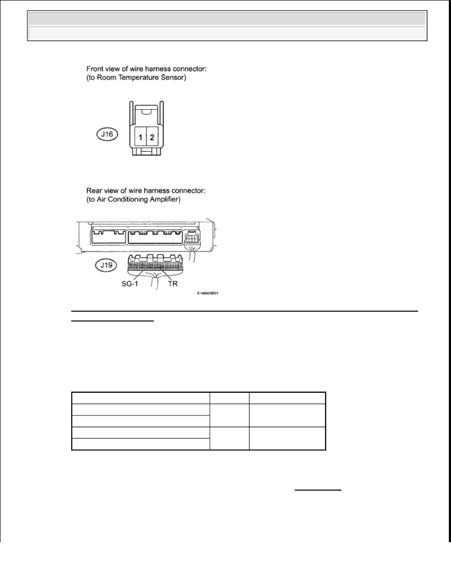
Fig. 31: Identifying Terminals Of J16 Room Temperature Sensor And J19 Air Conditioning
Amplifier Connectors
Courtesy of TOYOTA MOTOR SALES, U.S.A., INC.
c. Measure the resistance according to the value(s) in the table below.
Standard Resistance
TESTER CONNECTION SPECIFIED CONDITION CHART
NG: REPAIR OR REPLACE HARNESS OR CONNECTOR
OK: REPLACE AIR CONDITIONING AMPLIFIER (See REMOVAL )
DTC B1412/12 AMBIENT TEMPERATURE SENSOR CIRCUIT
DESCRIPTION
Tester Connection
Condition Specified Condition
J16-1 - J19-29 (TR)
Always
Below 1 ohms
J16-2 - J19-34 (SG-1)
J16-1 or J19-29 (TR) - Body ground
Always
10 kohms or higher
J16-2 or J19-34 (SG-1) - Body ground
2009 Toyota Tundra
2009 HVAC Air Conditioning - Tundra

The ambient temperature sensor is installed in front of the condenser to detect the ambient temperature which is
used to control the air conditioner "AUTO" mode. This sensor is connected to the air conditioning amplifier and
detects fluctuations in the ambient temperature. This data is used for controlling the cabin temperature. The
sensor sends a signal to the air conditioning amplifier. The resistance of the ambient temperature sensor changes
in accordance with the ambient temperature. As the temperature decreases, the resistance increases. As the
temperature increases, the resistance decreases.
The air conditioning amplifier applies voltage (5 V) to the ambient temperature sensor and reads voltage
changes as the resistance of the ambient temperature sensor changes.
DTC DETECTION CONDITION CHART
WIRING DIAGRAM
Fig. 32: Ambient Temperature Sensor - Wiring Diagram
Courtesy of TOYOTA MOTOR SALES, U.S.A., INC.
INSPECTION PROCEDURE
1. READ VALUE USING TECHSTREAM (AMBIENT TEMPERATURE SENSOR)
a. Use the Data List to check if the ambient temperature sensor is functioning properly.
Air Conditioner
DATA LIST
DTC
DTC Detection Condition
Trouble Area
B1412/12
Open or short in ambient
temperature sensor circuit
Ambient temperature sensor
Harness or connector
between ambient temperature
sensor and air conditioning
amplifier
Air conditioning amplifier
2009 Toyota Tundra
2009 HVAC Air Conditioning - Tundra

OK:
The display is as specified in the normal condition.
Result
RESULT REFERENCE
B: PROCEED TO NEXT CIRCUIT INSPECTION SHOWN IN PROBLEM SYMPTOMS
TABLE (See PROBLEM SYMPTOMS TABLE )
C: REPLACE AIR CONDITIONING AMPLIFIER (See REMOVAL )
A: Go to Next Step
2. INSPECT AMBIENT TEMPERATURE SENSOR
a. Remove the ambient temperature sensor (see REMOVAL ).
Tester
Display
Measurement Item/Range
Normal Condition
Diagnostic Note
Ambient Temp
Sensor
Ambient temperature
sensor/Min.: -23.3°C (-9.94°F)
Max.: 65.95°C (150.71°F)
Actual ambient
temperature is displayed
Open in circuit: -23.3°
C (-9.94°F)
Short in circuit: 65.95°
C (150.71°F)
Result
Proceed to
NG
A
OK (Checking from the PROBLEM SYMPTOMS TABLE)
B
OK (Checking from the DTC)
C
2009 Toyota Tundra
2009 HVAC Air Conditioning - Tundra
Нет комментариевНе стесняйтесь поделиться с нами вашим ценным мнением.
Текст