Toyota Tundra. Manual — part 512
NG: REPAIR OR REPLACE HARNESS OR CONNECTOR
OK: Go to Next Step
2. INSPECT SPIRAL CABLE
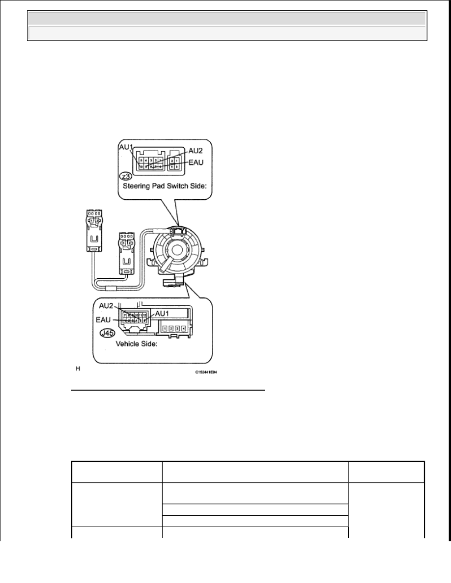
a. Disconnect the z3 and J45 cable connectors.
Fig. 174: Identifying Z3 And J45 Cable Connectors
Courtesy of TOYOTA MOTOR SALES, U.S.A., INC.
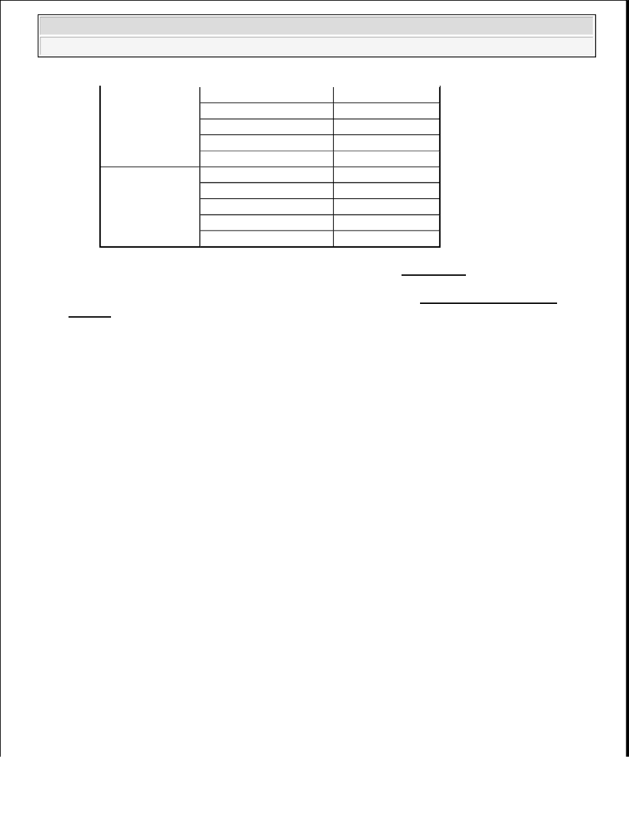
b. Measure the resistance according to the value(s) in the table below.
Standard resistance
SPIRAL CABLE TESTER CONNECTION SPECIFIED CONDITION
Tester Connection
Condition
Specified
Condition
J45-4(EAU)-Z3-8(EAU)
Spiral cable is turned 2.5 rotations
counterclockwise
Spiral cable is centered
Spiral cable is turned 2.5 rotations clockwise
2009 Toyota Tundra
2009 ACCESSORIES AND EQUIPMENT Navigation - Tundra

NG: REPLACE SPIRAL CABLE SUB-ASSEMBLY (See REMOVAL )
OK: Go to Next Step
3. INSPECT STEERING PAD SWITCH ASSEMBLY
Fig. 175: Identifying Steering Pad Switch Assembly
Courtesy of TOYOTA MOTOR SALES, U.S.A., INC.
a. Disconnect the z3 switch connector.
b. Measure the resistance according to the value(s) in the table below.
Standard resistance
STEERING PAD SWITCH ASSEMBLY
J45-5(AU2)-z3-9(AU2)
Spiral cable is turned 2.5 rotations
counterclockwise
Below 1 ohms
Spiral cable is centered
Spiral cable is turned 2.5 rotations clockwise
J45-6(AU1)-z3-10
(AU1)
Spiral cable is turned 2.5 rotations
counterclockwise
Spiral cable is centered
Spiral cable is turned 2.5 rotations clockwise
CAUTION: The spiral cable is an important part of the SRS airbag system.
Incorrect removal or installation of the spiral cable may prevent
the airbag from deploying. Be sure to read the PRECAUTION for
the supplemental restraint system (see PRECAUTION ).
Tester Connection
Switch Condition
Specified Condition
2009 Toyota Tundra
2009 ACCESSORIES AND EQUIPMENT Navigation - Tundra
NG: REPLACE STEERING PAD SWITCH ASSEMBLY (See REMOVAL )
OK: PROCEED TO NEXT CIRCUIT INSPECTION SHOWN IN PROBLEM SYMPTOMS
TABLE
ILLUMINATION CIRCUIT
DESCRIPTION
Power is supplied to the illumination circuit for the navigation receiver and steering pad switch when the light
control switch is in the TAIL or HEAD position.
WIRING DIAGRAM
9(AU2)-8(EAU)
No switch is pushed
100 kohms or higher
MODE switch pushed
Below 1 ohms
On Hook switch pushed
329 ohms
Off Hook switch pushed
1000 ohms
Voice switch is pushed
3110 ohms
10(AU1)-8(EAU)
No switch is pushed
100 kohms or higher
Seek+ switch pushed
Below 1 ohms
Seek- switch pushed
329 ohms
Volume+ switch is pushed
1000 ohms
Volume- switch is pushed
3110 ohms
2009 Toyota Tundra
2009 ACCESSORIES AND EQUIPMENT Navigation - Tundra

Fig. 176: Illumination Circuit - Wiring Diagram
Courtesy of TOYOTA MOTOR SALES, U.S.A., INC.
INSPECTION PROCEDURE
1. CHECK ILLUMINATION
a. Check if the illumination for the navigation receiver, steering pad switch, glove box light or other
parts (seat heater switch, room light switch, etc.) come on when the light control switch is turned to
the HEAD or TAIL position.
Result
CAUTION: The vehicle is equipped with an SRS (Supplemental Restraint System)
which includes components such as airbags. Before servicing (including
removal or installation of parts), be sure to read the PRECAUTION in the
Supplemental Restraint System (see PRECAUTION ).
2009 Toyota Tundra
2009 ACCESSORIES AND EQUIPMENT Navigation - Tundra
Нет комментариевНе стесняйтесь поделиться с нами вашим ценным мнением.
Текст