Toyota Tundra. Manual — part 2413
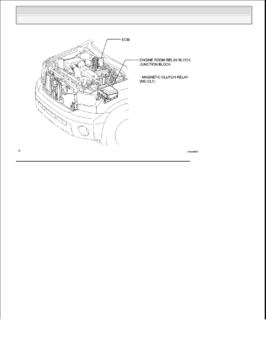
Fig. 87: Identifying Air Conditioning System (Manual) Parts Location (4 Of 4)
Courtesy of TOYOTA MOTOR SALES, U.S.A., INC.
SYSTEM DIAGRAM
2009 Toyota Tundra
2009 HVAC Air Conditioning - Tundra
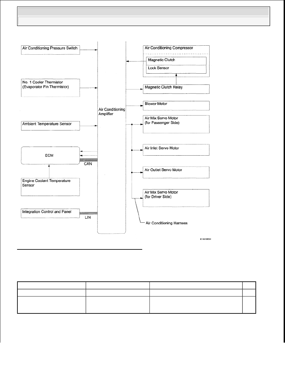
Fig. 88: Air Conditioning System (Manual) Diagram
Courtesy of TOYOTA MOTOR SALES, U.S.A., INC.
Communication table
COMMUNICATION CHART
SYSTEM DESCRIPTION
1. GENERAL
Sender
Receiver
Signal
Line
Integration Control and Panel Air Conditioning Amplifier
A/C control signal
LIN
ECM
Air Conditioning Amplifier
Engine speed
Engine coolant temperature signal
CAN
2009 Toyota Tundra
2009 HVAC Air Conditioning - Tundra

a. The air conditioning system has the following controls:
SYSTEM REFERENCE CHART
2. MODE POSITION AND DAMPER OPERATION (for Regular Cab and Double Cab)
a. Mode Position and Damper Operation
Control
Outline
Manual
Control
The air conditioning amplifier controls the damper positions (air inlet control
damper, air mix control damper and mode control damper) and blower speed in
accordance with the positions of the switches (temperature control switch, blower
switch, mode select switch and air inlet control switch).
MAX A/C
Control
When the temperature control switch is in the MAX A/C position, the air
conditioning amplifier turns the compressor on and activates the servo motor (air
inlet) to set the air inlet control damper to the RECIRC position, improving the
cooling efficiency.
Compressor
Control
Through the calculation of the target evaporator temperature based on various
sensor signals, the air conditioning amplifier optimally controls the discharge
capacity by regulating the opening extent of the air conditioning compressor
solenoid valve.
The air conditioning amplifier compares the pulley speed signals, which are
transmitted by the lock sensor located on the air conditioning compressor, with the
engine speed signals, which are transmitted by the ECM (crankshaft position
sensor). When the air conditioning amplifier determines that the pulley is locked, it
turns off the magnetic clutch.
Self-
Diagnosis
A DTC (Diagnostic Trouble Code) is stored in the memory when the air
conditioning amplifier detects a problem with the air conditioning system.
2009 Toyota Tundra
2009 HVAC Air Conditioning - Tundra
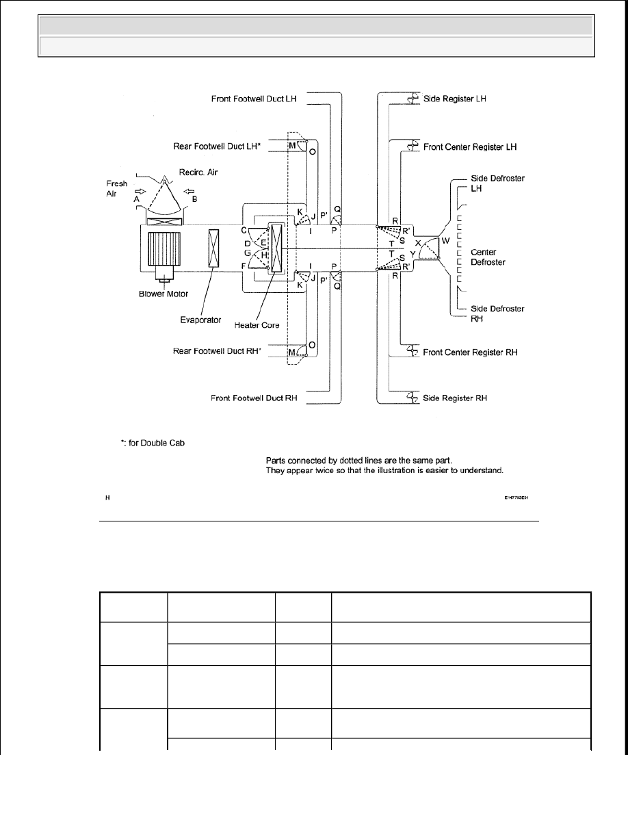
Fig. 89: Mode Position And Damper Operation (For Regular Cab And Double Cab)
Courtesy of TOYOTA MOTOR SALES, U.S.A., INC.
Functions of Main Dampers:
FUNCTIONS OF MAIN DAMPERS
Control
Damper
Operation Position
Damper
Position
Operation
Air Inlet
Control
Damper
FRESH
B
Brings in fresh air.
RECIRC
A
Recirculates internal air.
Air Mix
Control
Damper
MAX COLD to
MAX HOT
Temperature Setting
C - E
F - H
I - K
Varies the mixture ratio of fresh air and recirculated
air in order to regulate the temperature
continuously from HOT to COLD.
FACE
O, P, T, W
Air blows out of the front center register, side
registers, and footwell ducts.*1
2009 Toyota Tundra
2009 HVAC Air Conditioning - Tundra
Нет комментариевНе стесняйтесь поделиться с нами вашим ценным мнением.
Текст