Toyota Tundra. Manual — part 598

b. Check that the accessory meter buzzer operates normally.
OK: Accessory meter buzzer operates normally.
NG: PROCEED TO NEXT CIRCUIT INSPECTION SHOWN IN PROBLEM SYMPTOMS
TABLE
OK: END (ACCESSORY METER IS DEFECTIVE)
CLEARANCE WARNING ECU POWER SOURCE CIRCUIT
DESCRIPTION
This circuit is the power source circuit to operate the clearance warning ECU.
WIRING DIAGRAM
Fig. 40: Clearance Warning ECU Power Source - Wiring Diagram
Courtesy of TOYOTA MOTOR SALES, U.S.A., INC.
INSPECTION PROCEDURE
1. CHECK FUSE (ECU-IG No. 1)
a. Remove the ECU-IG No. 1 fuse from the main body ECU.
b. Measure the resistance according to the value(s) in the table below.
Standard resistance
FUSE (ECU-IG No. 1) RESISTANCE SPECIFICATION
NG: REPLACE FUSE
Tester Connection Condition Specified Condition
ECU-IG No. 1 fuse Always
Below 1 ohms
2009 Toyota Tundra
2009 ACCESSORIES AND EQUIPMENT Parking Assist/Monitoring - Tundra

OK: Go to next step
2. CHECK HARNESS AND CONNECTOR (MONITOR SWITCH - BATTERY)
a. Disconnect the L2 switch connector.
b. Measure the voltage according to the value(s) in the table below.
Standard voltage
HARNESS AND CONNECTOR (MONITOR SWITCH - BATTERY) VOLTAGE
SPECIFICATION
Fig. 41: Identifying L2 Switch Connector Terminals
Courtesy of TOYOTA MOTOR SALES, U.S.A., INC.
NG: REPAIR OR REPLACE HARNESS OR CONNECTOR
OK: Go to next step
3. INSPECT DRIVE MONITOR SWITCH
a. Remove the drive monitor switch (see REMOVAL ).
b. Measure the resistance according to the value(s) in the table below.
Standard resistance
DRIVE MONITOR SWITCH RESISTANCE SPECIFICATION
Tester Connection
Switch Condition Specified Condition
L2-7 (IG) - Body ground Ignition switch ON
11 to 14 V
Tester Connection
Switch Condition
Specified Condition
7 (IG) - 8 (SK)
Clearance sonar main switch ON
Below 1 ohms
Clearance sonar main switch OFF 10 kohms or higher
2009 Toyota Tundra
2009 ACCESSORIES AND EQUIPMENT Parking Assist/Monitoring - Tundra

Fig. 42: Identifying Drive Monitor Switch Connector Terminals
Courtesy of TOYOTA MOTOR SALES, U.S.A., INC.
NG: REPLACE DRIVE MONITOR SWITCH (See REMOVAL )
OK: Go to next step
4. CHECK HARNESS AND CONNECTOR (ECU - MONITOR SWITCH AND BODY GROUND)
a. Disconnect the J35 ECU connector.
b. Disconnect the L2 switch connector.
c. Measure the resistance according to the value(s) in the table below.
Standard resistance
HARNESS AND CONNECTOR (ECU - MONITOR SWITCH AND BODY GROUND)
RESISTANCE SPECIFICATION
Tester Connection
Condition Specified Condition
J35-10 (IG) - L2-8 (SK)
Always
Below 1 ohms
J35-10 (IG) - Body ground Always
10 kohms or higher
J35-21 (E) - Body ground
Always
Below 1 ohms
2009 Toyota Tundra
2009 ACCESSORIES AND EQUIPMENT Parking Assist/Monitoring - Tundra
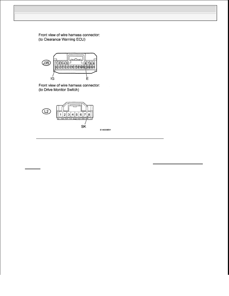
Fig. 43: Identifying J35 ECU And L2 Switch Connector Terminals
Courtesy of TOYOTA MOTOR SALES, U.S.A., INC.
NG: REPAIR OR REPLACE HARNESS OR CONNECTOR
OK: PROCEED TO NEXT CIRCUIT INSPECTION SHOWN IN PROBLEM SYMPTOMS
TABLE
INDICATOR CIRCUIT
DESCRIPTION
The sonar ON/OFF indicator light and warning indicator lights are installed in the accessory meter.
WIRING DIAGRAM
2009 Toyota Tundra
2009 ACCESSORIES AND EQUIPMENT Parking Assist/Monitoring - Tundra
Нет комментариевНе стесняйтесь поделиться с нами вашим ценным мнением.
Текст