Toyota Tundra. Manual — part 1269

Fig. 264: Identifying IGN Fuse
OK : Go to next step.
7. CHECK HARNESS AND CONNECTOR (INTEGRATION RELAY - ECM, INTEGRATION
RELAY - BODY GROUND)
a. Remove the integration relay from the engine room junction block (See ON-VEHICLE
INSPECTION ).
b. Disconnect the A24 ECM connector.
c. Measure the resistance according to the value (s) in the table below.
Standard resistance (Check for open)
TESTER CONNECTION SPECIFIED CONDITION
Standard resistance (Check for short)
TESTER CONNECTION SPECIFIED CONDITION
NG : REPAIR OR REPLACE HARNESS OR CONNECTOR
Tester Connection
Condition Specified Condition
1B-8 - A24-28 (IGSW) Always
Below 1 ohms
Tester Connection
Condition Specified Condition
1B-8 or A24-28 (IGSW) - Body ground Always
10 kohms or higher
2008 Toyota Tundra
2008 ENGINE PERFORMANCE Engine Control System (1GR-FE) - Tundra

Fig. 265: Checking Harness & Connector (Integration Relay - ECM, Integration Relay - Body
Ground)
OK : Go to next step.
8. CHECK HARNESS AND CONNECTOR (INTEGRATION RELAY - IGNITION SWITCH
ASSEMBLY)
a. Check the harness and the connectors between the integration relay and the ignition switch.
1. Remove the integration relay from the engine room junction block (See ON-VEHICLE
INSPECTION ).
2. Disconnect the J9 ignition switch connector.
2008 Toyota Tundra
2008 ENGINE PERFORMANCE Engine Control System (1GR-FE) - Tundra

3. Measure the resistance according to the value (s) in the table below.
Standard resistance (Check for open)
TESTER CONNECTION SPECIFIED CONDITION
Standard resistance (Check for short)
TESTER CONNECTION SPECIFIED CONDITION
b. Check the harness and connectors between the integration relay and body ground.
1. Measure the resistance according to the value (s) in the table below.
Standard resistance (Check for open)
TESTER CONNECTION SPECIFIED CONDITION
NG : REPAIR OR REPLACE HARNESS OR CONNECTOR
Tester Connection Condition Specified Condition
1B-6 - J9-6 (IG2)
Always
Below 1 ohms
Tester Connection
Condition Specified Condition
1B-6 or J9-6 (IG2) - Body ground Always
10 kohms or higher
Tester Connection Condition Specified Condition
1B-7 - Body ground Always
Below 1 ohms
2008 Toyota Tundra
2008 ENGINE PERFORMANCE Engine Control System (1GR-FE) - Tundra
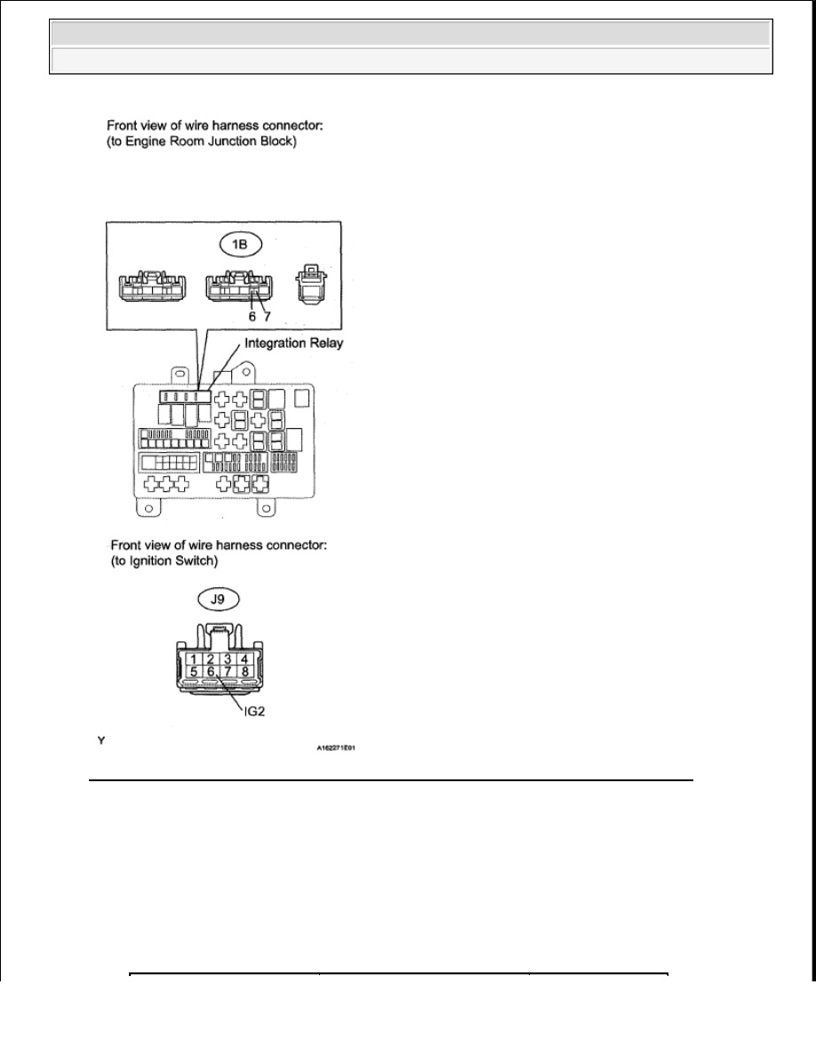
Fig. 266: Checking Harness & Connector (Integration Relay - Ignition Switch Assembly)
OK : Go to next step.
9. INSPECT IGNITION SWITCH ASSEMBLY
a. Disconnect the J9 ignition switch connector.
b. Measure the resistance according to the value (s) in the table below.
Standard resistance
TESTER CONNECTION SPECIFIED CONDITION
2008 Toyota Tundra
2008 ENGINE PERFORMANCE Engine Control System (1GR-FE) - Tundra
Нет комментариевНе стесняйтесь поделиться с нами вашим ценным мнением.
Текст