Toyota Tundra. Manual — part 2402

RESULT REFERENCE
B: PROCEED TO NEXT CIRCUIT INSPECTION SHOWN IN PROBLEM
SYMPTOMS TABLE (See PROBLEM SYMPTOMS TABLE )
C: REPLACE AIR CONDITIONING AMPLIFIER (See REMOVAL )
A: REPLACE AIR CONDITIONING PRESSURE SWITCH (See REMOVAL )
DTC B1424/24 SOLAR SENSOR CIRCUIT (DRIVER SIDE)
DESCRIPTION
The solar sensor, which is installed on the upper side of the instrument panel, detects sunlight and controls the
air conditioning in AUTO mode. The output current from the solar sensor varies according to the amount of
sunlight. When the sunlight increases, the output current increases. As the sunlight decreases, the output current
decreases. The air conditioning amplifier detects output current from the solar sensor.
Fig. 52: Solar Sensor Output Voltage Graph
Courtesy of TOYOTA MOTOR SALES, U.S.A., INC.
DTC DETECTION CONDITION CHART
Result
Proceed to
NG
A
OK (Checking from the PROBLEM SYMPTOMS TABLE)
B
OK (Checking from the DTC)
C
DTC
DTC Detection Condition
Trouble Area
Automatic light control
sensor (solar sensor)
Harness and connector
between solar sensor and air
2009 Toyota Tundra
2009 HVAC Air Conditioning - Tundra
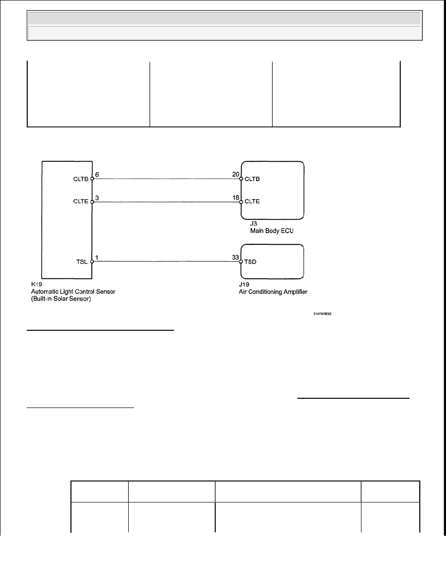
WIRING DIAGRAM
Fig. 53: Solar Sensor - Wiring Diagram
Courtesy of TOYOTA MOTOR SALES, U.S.A., INC.
INSPECTION PROCEDURE
HINT:
If DTC B1244 is output at the same time, troubleshoot DTC B1244 first (see DTC B1244 LIGHT SENSOR
CIRCUIT MALFUNCTION ).
1. READ VALUE USING TECHSTREAM (SOLAR SENSOR (for Driver Side))
a. Use the Data List to check if the driver side solar sensor is functioning properly.
Air Conditioner
DATA LIST
B1424/24
Open or short in driver side solar
sensor circuit
conditioning amplifier
Harness and connector
between solar sensor and
main body ECU
Main body ECU
Air conditioning amplifier
Tester Display
Measurement
Item/Range
Normal Condition
Diagnostic
Note
Solar Sensor
Driver side solar
sensor/Min.: 0
Driver side solar sensor voltage
Open in circuit:
0
2009 Toyota Tundra
2009 HVAC Air Conditioning - Tundra

OK:
The display is as specified in the normal condition.
Result
RESULT REFERENCE
B: PROCEED TO NEXT CIRCUIT INSPECTION SHOWN IN PROBLEM SYMPTOMS
TABLE (See PROBLEM SYMPTOMS TABLE )
C: REPLACE AIR CONDITIONING AMPLIFIER (See REMOVAL )
A: Go to Next Step
2. CHECK HARNESS AND CONNECTOR (SOLAR SENSOR)
a. Disconnect the K19 solar sensor connector.
Fig. 54: Identifying Terminals Of K19 Solar Sensor Connector
Courtesy of TOYOTA MOTOR SALES, U.S.A., INC.
b. Measure the resistance according to the value(s) in the table below.
Standard Resistance
TESTER CONNECTION SPECIFIED CONDITION CHART
(D Side)
Max.: 255
increases as brightness increases
Short in circuit:
255
Result
Proceed to
NG
A
OK (Checking from the PROBLEM SYMPTOMS TABLE)
B
OK (Checking from the DTC)
C
Tester Connection
Condition Specified Condition
K19-3 (CLTE) -Body ground Always
Below 1 ohms
2009 Toyota Tundra
2009 HVAC Air Conditioning - Tundra
c. Measure the voltage according to the value(s) in the table below.
Standard Voltage
TESTER CONNECTION SPECIFIED CONDITION CHART
NG: Go to step 5
OK: Go to Next Step
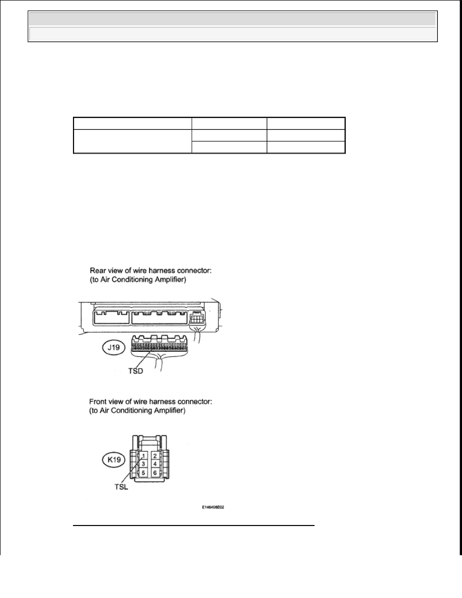
3. CHECK HARNESS AND CONNECTOR (AIR CONDITIONING AMPLIFIER - SOLAR
SENSOR)
a. Disconnect the J19 air conditioning amplifier connector.
b. Disconnect the K19 solar sensor connector.
Fig. 55: Identifying Terminals Of K19 Solar Sensor Connector
Courtesy of TOYOTA MOTOR SALES, U.S.A., INC.
Tester Connection
Switch Condition Specified Condition
K19-6 (CLTB) - K19-3 (CLTE)
Ignition switch ON
11 to 14 V
Ignition switch OFF
Below 1 V
2009 Toyota Tundra
2009 HVAC Air Conditioning - Tundra
Нет комментариевНе стесняйтесь поделиться с нами вашим ценным мнением.
Текст