Toyota Tundra. Manual — part 1642

NG: REPAIR OR REPLACE HARNESS OR CONNECTOR
OK: Go to Next Step
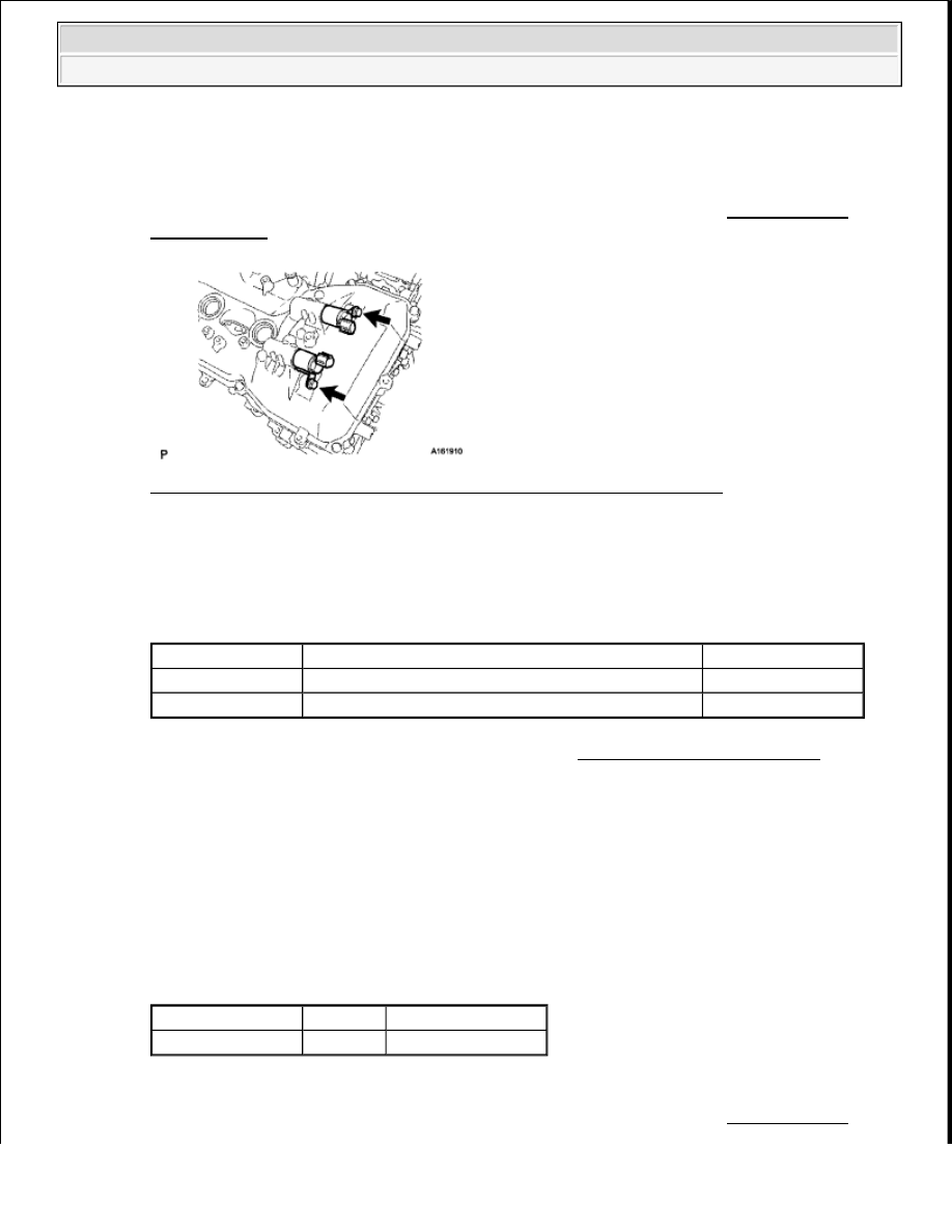
9. INSPECT FUEL PUMP
a. Inspect the fuel pump (see REMOVAL ).
NG: REPLACE FUEL PUMP (See REMOVAL )
OK: Go to Next Step
10. CHECK HARNESS AND CONNECTOR (FUEL PUMP ECU - ECM AND BODY GROUND)
a. Disconnect the R7 fuel pump ECU connector.
b. Disconnect the A24 ECM connector.
Fig. 309: Identifying R7 Fuel Pump ECU And A24 ECM Connector Terminals
Courtesy of TOYOTA MOTOR SALES, U.S.A., INC.
c. Measure the resistance according to the value (s) in the table below.
Standard resistance
RESISTANCE SPECIFIED CONDITIONS
NG: REPAIR OR REPLACE HARNESS OR CONNECTOR
OK: Go to Next Step
11. REPLACE FUEL PUMP ECU
Tester Connection
Condition Specified Condition
R7-1 (FPC) - A24-52 (FPC)
Always
Below 1 ohms
R7-2 (DI) - A24-18 (DI)
Always
Below 1 ohms
R7-3 (E) - Body ground
Always
Below 1 ohms
R7-1 (FPC) or A24-52 (FPC) - Body ground Always
10 kohms or more
R7-2 (DI) or A24-18 (DI) - Body ground
Always
10 kohms or more
2009 Toyota Tundra
2009 ENGINE PERFORMANCE Engine Control System (3UR-FBE) - Tundra
Saturday, June 19, 2010 7:34:49 PM
Page 661
© 2006 Mitchell Repair Information Company, LLC.

a. Replace the fuel pump ECU (see REMOVAL ).
12. CONFIRM WHETHER MALFUNCTION HAS BEEN SUCCESSFULLY REPAIRED
a. Check the fuel pump operation.
OK:
Malfunction has been repaired successfully.
NG: REPLACE ECM (See REMOVAL )
OK: END
13. CHECK HARNESS AND CONNECTOR (CIRCUIT OPENING RELAY - FUEL PUMP RELAY
AND IGN FUSE)
a. Remove the circuit opening relay (C/OPN) from the engine room relay block (see ON-VEHICLE
INSPECTION ).
b. Remove the fuel pump relay (F/PMP) from the engine room relay block (see ON-VEHICLE
INSPECTION ).
Fig. 310: Identifying Circuit Opening And Fuel Pump Relay
Courtesy of TOYOTA MOTOR SALES, U.S.A., INC.
c. Remove the IGN fuse from the engine room relay block.
d. Measure the resistance according to the value (s) in the table below.
Standard resistance
RESISTANCE SPECIFIED CONDITIONS
NG: REPAIR OR REPLACE HARNESS OR CONNECTOR
Tester Connection
Condition Specified Condition
C/OPN relay (1) - IGN fuse (2)
Always
Below 1 ohms
C/OPN relay (3) - F/PMP relay (3)
Always
Below 1 ohms
C/OPN relay (1) or IGN fuse (2) - Body ground
Always
10 kohms or more
C/OPN relay (3) or F/PMP relay (3) - Body ground Always
10 kohms or more
2009 Toyota Tundra
2009 ENGINE PERFORMANCE Engine Control System (3UR-FBE) - Tundra
Saturday, June 19, 2010 7:34:49 PM
Page 662
© 2006 Mitchell Repair Information Company, LLC.
OK: Go to Next Step
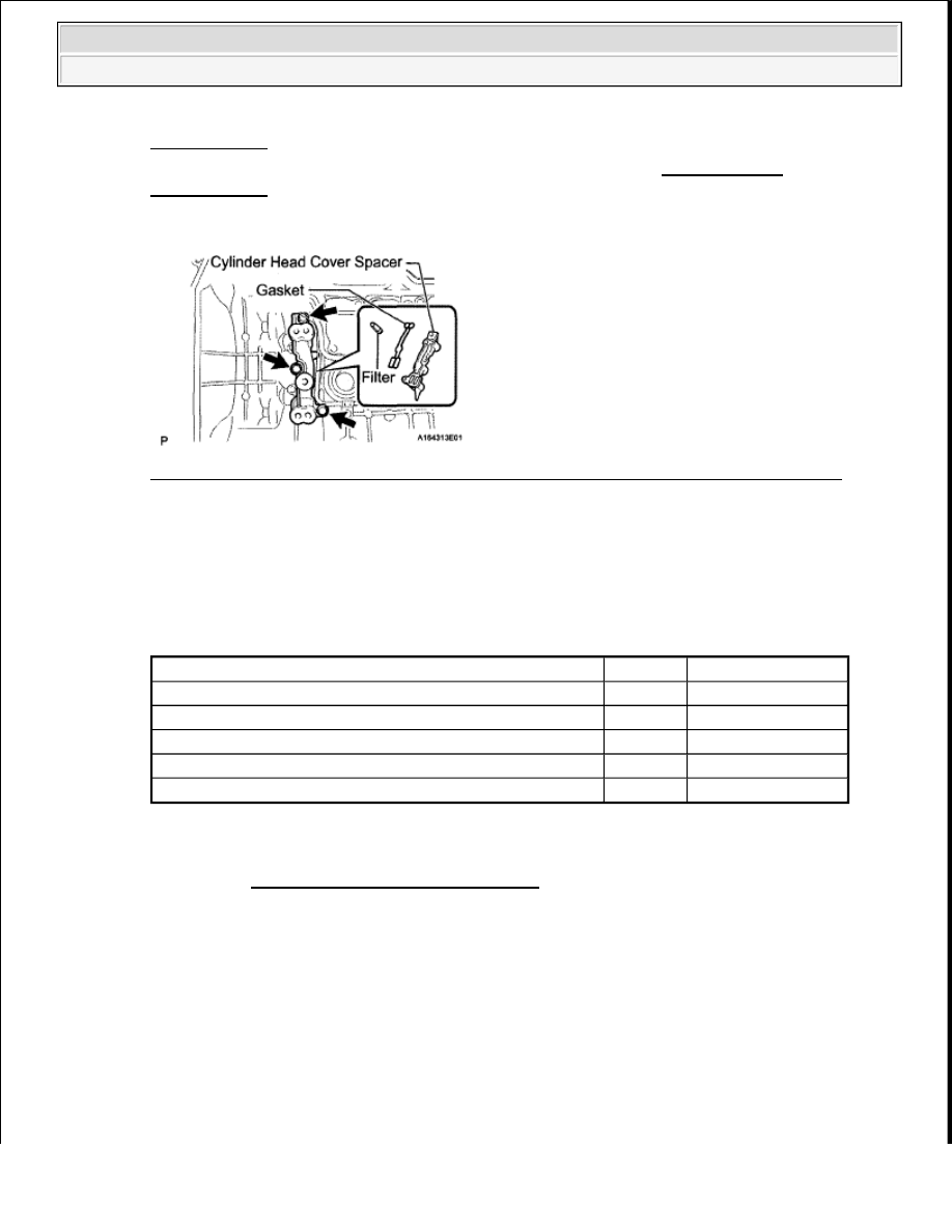
14. INSPECT FUEL PUMP RELAY (F/PMP)
a. Remove the fuel pump relay (F/PMP) from the engine room relay block (see ON-VEHICLE
INSPECTION ).
Fig. 311: Identifying Fuel Pump Relay (F/PMP) Circuit With Terminals
Courtesy of TOYOTA MOTOR SALES, U.S.A., INC.
b. Measure the resistance according to the value (s) in the table below.
Standard resistance
RESISTANCE SPECIFIED CONDITIONS
NG: REPLACE FUEL PUMP RELAY (F/PMP) (See ON-VEHICLE INSPECTION )
OK: Go to Next Step
15. CHECK HARNESS AND CONNECTOR (FUEL PUMP RELAY - INTEGRATION RELAY,
BATTERY AND BODY GROUND)
a. Remove the F/PMP fuse from the engine room relay block.
b. Measure the resistance according to the value (s) in the table below.
Standard resistance
RESISTANCE SPECIFIED CONDITIONS
c. Reinstall the F/PMP fuse.
d. Remove the fuel pump relay (F/PMP) from the engine room relay block (see ON-VEHICLE
Tester Connection
Condition
Specified Condition
3 - 5
When no battery voltage applied to terminals 1 and 2 10 kohms or higher
3 - 5
When battery voltage applied to terminals 1 and 2
Below 1 ohms
Tester Connection Condition Specified Condition
F/PMP fuse
Always
Below 1 ohms
2009 Toyota Tundra
2009 ENGINE PERFORMANCE Engine Control System (3UR-FBE) - Tundra
Saturday, June 19, 2010 7:34:49 PM
Page 663
© 2006 Mitchell Repair Information Company, LLC.
INSPECTION ).
e. Remove the integration relay from the engine room relay block (see ON-VEHICLE
INSPECTION ).
f. Disconnect the 1B integration relay connector.
Fig. 312: Identifying Fuel Pump Relay And 1B Integration Relay Connector Terminals
Courtesy of TOYOTA MOTOR SALES, U.S.A., INC.
g. Disconnect the cable from the battery positive (+) terminal.
h. Measure the resistance according to the value (s) in the table below.
Standard resistance
RESISTANCE SPECIFIED CONDITIONS
NG: REPAIR OR REPLACE HARNESS OR CONNECTOR
OK: GO TO ECM POWER SOURCE CIRCUIT
FUEL INJECTOR CIRCUIT
DESCRIPTION
The fuel injectors are located on the intake manifold. They inject fuel into the cylinders based on the signals
from the ECM.
WIRING DIAGRAM
Tester Connection
Condition Specified Condition
F/PMP relay (1) - 1B-4
Always
Below 1 ohms
F/PMP relay (5) - Positive (+) battery cable
Always
Below 1 ohms
F/PMP relay (2) - Body ground
Always
Below 1 ohms
F/PMP relay (1) or 1B-4-Body ground
Always
10 kohms or higher
F/PMP relay (5) or Positive (+) battery cable - Body ground Always
10 kohms or higher
2009 Toyota Tundra
2009 ENGINE PERFORMANCE Engine Control System (3UR-FBE) - Tundra
Saturday, June 19, 2010 7:34:49 PM
Page 664
© 2006 Mitchell Repair Information Company, LLC.
Нет комментариевНе стесняйтесь поделиться с нами вашим ценным мнением.
Текст