Suzuki Grand Vitara JB627. Manual — part 409
10A-2 Cruise Control System:
General Description
Cruise Control System Construction
S6JB0BA101001
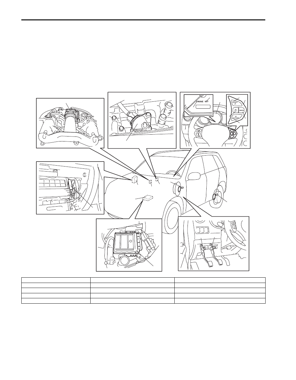
The cruise control system is a device which maintains a preset vehicle speed while driving at a high speed, e.g., on a
highway. It allows the driver to drive his vehicle at a constant speed of 40 km/h (25 mile/h) or higher without
depressing the accelerator pedal. The system also has such functions as to change the vehicle speed without
operating the accelerator pedal (but using SET/COAST and RES/ACC switches), cancel cruise control (CANCEL
switch) and resume the speed in memory automatically after cruise control is cancelled (RES/ACC switch). The
system mainly consists of electric throttle body assembly, ECM, cruise control switch (MAIN (ON/OFF) switch, SET/
COAST switch, RES/ACC switch and CANCEL switch), etc.
15
10
10
15
14
9
11
12
13
3
5
8
6
7
4
1
2
9
13
14
I6JB0BA10001-01
1. Combination meter
6. MAIN (ON/OFF) switch
11. Brake light switch with brake pedal position switch
2. “CRUISE” indicator light
7. SET/COAST switch
12. Clutch pedal position switch (M/T model)
3. “SET” indicator light
8. CANCEL switch
13. ECM
4. Cruise control switch
9. Wheel speed sensor (vehicle speed signal)
14. Transmission range switch (A/T model)
5. RES/ACC switch
10. Electric throttle body
15. TCM (A/T model)

Cruise Control System: 10A-3
Components and Functions of Cruise Control System
S6JB0BA101002
Component
Function
ECM and electric throttle body
assembly
ECM executes centralized control over all functions including setting a constant speed,
resuming it, setting coast, cancelling cruise control limiting minimum speed.
ECM controls electric throttle valve opening to keep actual vehicle speed at set (target)
speed.
MAIN (ON/OFF) switch
This switch has a momentary contact type button to press cruise control
system ON and OFF.
SET/COAST switch
When this switch is pressed (ON) and then released (OFF) while vehicle is running at
a speed 40 km/h (25 mile/h) or higher, vehicle speed at that OFF moment is stored in
memory and it is maintained (constant cruising).
Pressing this switch (ON) continuously during constant cruising keeps slowing down
vehicle speed as long as it is ON. When it is released (OFF), vehicle speed at that
moment is stored in memory and vehicle starts constant cruising.
RES/ACC switch
When this switch is pressed (ON) during constant cruising, vehicle speed keeps
increasing as long as it is ON. When it is released (OFF), vehicle speed at that
moment is stored in memory and vehicle starts constant cruising. If vehicle speed is
higher than 40 km/h (25 mile/h) after cruise control is cancelled, pressing this switch
ON momentarily will resume the speed at which vehicle was running before
cancellation.
CANCEL switch
When this switch is pressed (ON), cruise control (throttle valve control) is cancelled.
Wheel speed sensor (vehicle
speed signal)
ECM receives speed sensor signal from ABS or ESP
® control module through CAN
communication and calculates vehicle speed using that signal.
Brake light switch
Brake light switch has 2 contact points. One contact point closes when brake pedal is
depressed to light brake light and provides a voltage signal to the ECM.
The other contact point (brake pedal position switch) opens when brake pedal is
depressed, to shut off power to cruise control of ECM, thereby cancelling cruise
control (throttle valve control).
This switch is installed to cancel cruise control (constant cruising).
Clutch pedal position switch
(M/T model)
When clutch pedal is depressed, clutch pedal position switch closes and provides a
ground signal to ECM.
ECM cancels cruise control (throttle valve control) when this signal is inputted.
Transmission range switch (A/
T model)
When selector lever is placed in either “P”, “R” or “N” position, transmission range
switch closes and provides a ground signal to TCM. TCM transmits signal from
transmission range switch to ECM through CAN communication. When ECM receives
a signal indicating that selector lever position is “P”, “R” or “N”, it cancels cruise control
(throttle valve control).
TCM (A/T model)
TCM receives the SET signal for the cruise control from ECM through CAN
communication. When TCM receives the SET signal from ECM, the gear shift control
is performed by using the gear shift map for the cruise control changed from the one
for normal gear shift. For details, refer to “Automatic Gear Shift Table in Section 5A”.
“CRUISE” indicator light
In the state with ignition switch ON and cruise control system OFF, pressing MAIN
(ON/OFF) switch once and releasing it will activate the cruise control system and ECM
will cause indicator light to light up.
“SET” indicator light
It lights up when cruise control (throttle valve control) is functioning.
10A-4 Cruise Control System:
Cancel Conditions of Cruise Control System
S6JB0BA101003
Constant cruising is cancelled under the following conditions.
• *Ignition switch is turned OFF.
• MAIN (ON/OFF) switch is turned OFF.
• Vehicle speed becomes lower than minimum operating speed (40 km/h (25 mile/h)).
• *Vehicle speed varies beyond cancel speed range
(–20 km/h (–12 mile/h)) from preset speed.
• *Brake pedal is depressed. (Brake light switch is turned ON).
• *Clutch pedal is depressed (Clutch pedal position switch is turned ON) (For M/T vehicle).
• *Selector lever is shifted to “P”, “R” or “N” range (For A/T vehicle).
• *CANCEL switch is turned ON.
• ESP
® is operating (if equipped).
NOTE
When constant cruising is cancelled under any condition with * (asterisk), vehicle speed before
cancellation can be resumed by operating RES/ACC switch, provided that vehicle speed is higher than
40 km/h (25 mile/h).
On-Board Diagnostic System Description
S6JB0BA101005
ECM diagnoses if there is any trouble in the cruise control system. When the ECM detects an abnormality in the cruise
control system, it saves the area where such abnormality has occurred as a DTC in its memory but MIL does not light
up. To read DTC, use SUZUKI scan tool referring to “DTC Check”.
Cruise Control System Diagnosis Introduction
S6JB0BA101006
To ensure that the trouble diagnosis is done accurately and smoothly, observe “Precautions in Diagnosing Troubles”,
“Cancel Conditions of Cruise Control System” and follow “Cruise Control System Check”.
Cruise Control System: 10A-5
Schematic and Routing Diagram
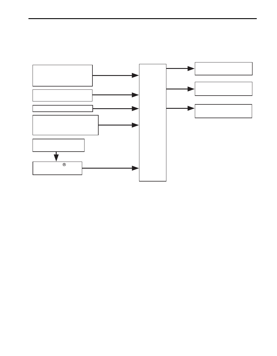
Cruise Control System Input / Output Diagram
S6JB0BA102002
Input
Output
MAIN (ON/OFF) switch
Cruise control switch
RES/ACC switch
SET/COAST switch
CANCEL switch
CPP switch
(M/T model)
Brake light switch
Wheel speed sensor
ABS or ESP
control module
(vehicle speed signal)
ECM
Electric throttle body
(throttle valve control)
Combination meter
(Indicator light control)
TCM (Shift control)
(A/T model)
(A/T model)
Transmission range switch
( or range signal)
“P”, “R”
“N”
I6JB0BA10002-01
Нет комментариевНе стесняйтесь поделиться с нами вашим ценным мнением.
Текст