Suzuki Grand Vitara JB627. Manual — part 66

1A-213 Engine General Information and Diagnosis:
26
WHT/
BLU
APP sensor signal
(main)
0.70 – 0.80 V
Ignition switch is at ON
position and accelerator
pedal is not depressed
after warmed up engine.
Output signal varies
linearly depending on the
accelerator pedal position.
3.33 – 4.07 V
Ignition switch is at ON
position and accelerator
pedal is at fully depressed
position after warmed up
engine.
27
ORN
Ground for APP
sensor (main)
Below 0.3 V
Ignition switch is at ON
position.
—
28
YEL/
RED
Fuel level sensor
signal
0 – 6 V
Ignition switch is at ON
position. (Voltage varies
depends on fuel level.)
Output signal varies
linearly depending on the
fuel level.
29
PPL/
WHT
Serial
communication line
of DLC
8 – 14 V
Ignition switch is at ON
position.
—
30
GRN/
WHT
Brake light switch
signal
0 – 1 V
Ignition switch is at ON
position and brake pedal is
not depressed.
—
10 – 14 V
Ignition switch is at ON
position and brake pedal is
depressed.
—
31
BLK/
WHT
Cruise control main
switch signal
(if equipped)
0 – 1 V
Ignition switch is at ON
position and cruise control
main switch is not pushed.
For details, refer to
“Inspection of Cruise
Control System Circuit in
Section 10A”.
10 – 14 V
Ignition switch is at ON
position and cruise control
main switch is kept in
push.
32
YEL/
GRN
Brake pedal
position switch
signal for cruise
control system
(if equipped)
0 – 1 V
Ignition switch is at ON
position and brake pedal is
depressed.
—
10 – 14 V
Ignition switch is at ON
position and brake pedal is
not depressed.
—
33
ORN/
BLU
Output for 5 V
power source of
APP sensor (sub)
4.5 – 5.5 V
Ignition switch is at ON
position.
—
34
BLU/
GRN
APP sensor signal
(sub)
0.37 – 0.38 V
Ignition switch is at ON
position and accelerator
pedal is not depressed
after warmed up engine.
Output signal varies
linearly depending on the
accelerator pedal position.
1.66 – 2.03 V
Ignition switch is at ON
position and accelerator
pedal is at fully depressed
position after warmed up
engine.
35
BLU/
YEL
Ground for APP
sensor (sub)
Below 0.3 V
Ignition switch is at ON
position.
—
36
—
—
—
—
—
Terminal
No.
Wire
color
Circuit
Normal voltage
Condition
Remarks
Engine General Information and Diagnosis: 1A-214
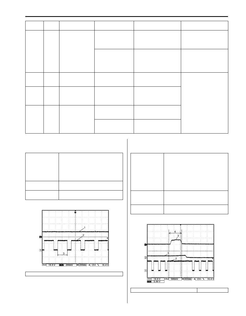
Reference waveform No.1
Oxygen (1) and heater output (2) signals of heated
oxygen sensor-2 (Bank-1 and Bank-2):
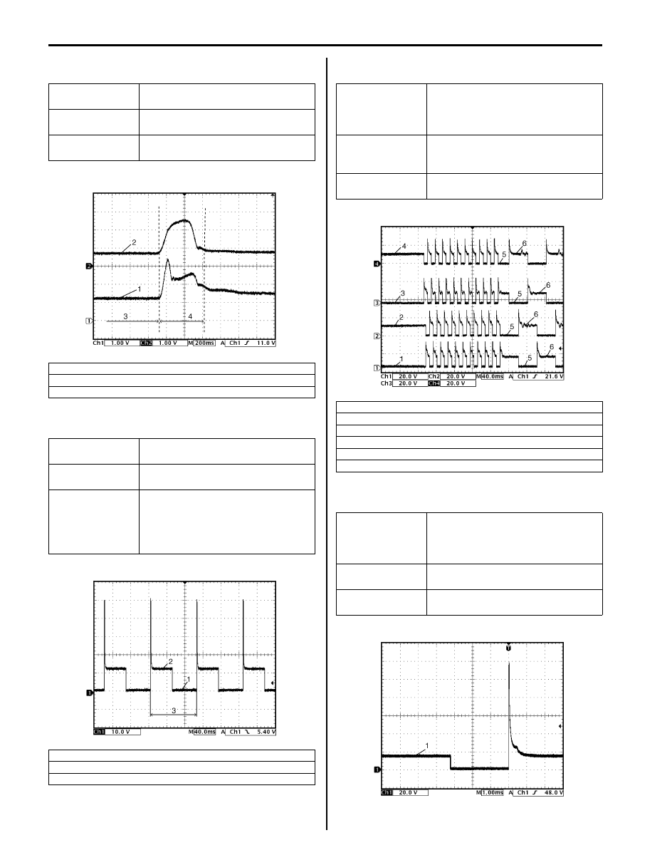
Reference waveform No.2
Oxygen signal (1) and heater output signal (2) of heated
oxygen sensor-2:
37
PNK
A/C compressor
relay output
(if equipped)
0 – 1 V
A/C switch is at OFF
position and blower
selector is at OFF position
while engine is running.
—
10 – 14 V
A/C switch is at ON
position and blower
selector is other than OFF
position while engine is
running.
—
38
BLK/
YEL
Ground for cruise
control command
switch (if equipped)
Below 1.3 V
Ignition switch is at ON
position.
For details, refer to
“Inspection of Cruise
Control System Circuit in
Section 10A”.
39
LT GRN
Cruise control
command switch
signal (if equipped)
4.5 – 5.5 V
Ignition switch is at ON
position and cruise control
command switch are not
pushed.
40
BLU
Clutch pedal
position switch
signal for cruise
control system
(if equipped)
0 – 1 V
Ignition switch is at ON
position and clutch pedal
is depressed.
10 – 14 V
Ignition switch is at ON
position and clutch pedal
is not depressed.
Terminal
No.
Wire
color
Circuit
Normal voltage
Condition
Remarks
Measurement
terminal
Bank-1
CH1: C37-1 or C37-2 to C37-81
CH2: C37-3 to C37-81
Bank-2
CH1: C37-20 or C37-21 to C37-81
CH2: C37-22 to C37-81
Oscilloscope
setting
CH1: 10 V/DIV, CH2: 200 mV/DIV
TIME: 200 ms/DIV
Measurement
condition
Engine is running at specified idle
speed after warmed up engine.
3. One duty cycle
I6JB01110065-02
Measurement
terminal
Bank-1
CH1: C37-1 or C37-2 to C37-81
CH2: C37-3 to C37-81
CH3: C37-46 to C37-81
Bank-2
CH1: C37-20 or C37-21 to C37-81
CH2: C37-22 to C37-81
CH3: C37-46 to C37-81
Oscilloscope
setting
CH1: 10 V/DIV, CH2: 500 mV/DIV,
CH3: 5 V/DIV
TIME: 400 ms/DIV
Measurement
condition
Engine is racing after warmed up
engine.
3. Throttle position sensor (main) signal
4. Racing
I6JB01110066-03
1A-215 Engine General Information and Diagnosis:
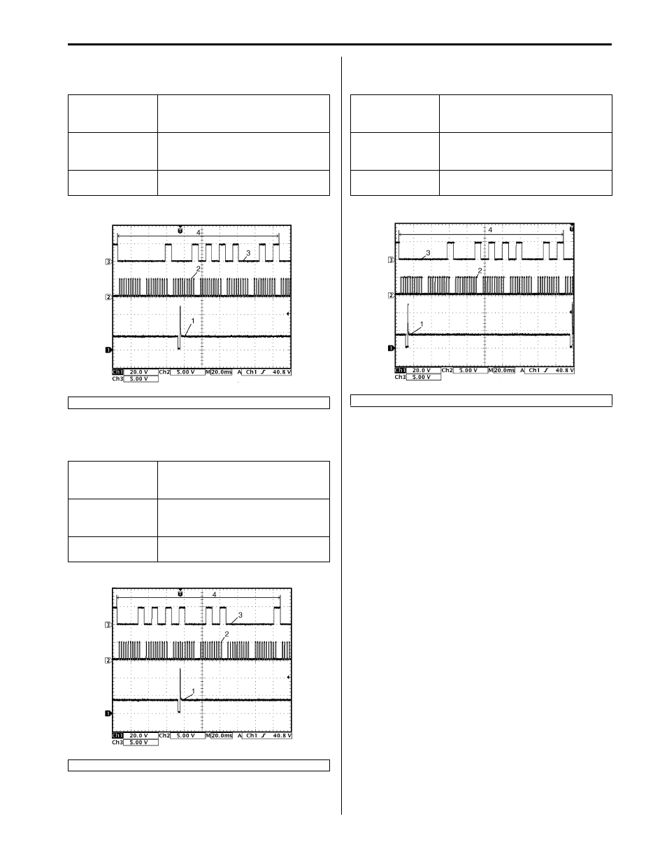
Reference waveform No.3
MAF sensor signal (1):
Reference waveform No.4
EVAP canister purge valve Signal:
Reference waveform No.5
EGR valve Signal:
Reference waveform No.6
Fuel injector signal:
Measurement
terminal
CH1: C37-4 to C37-23
CH2: C37-46 to C37-81
Oscilloscope
setting
CH1: 1 V/DIV, CH2: 1 V/DIV
TIME: 200 ms/DIV
Measurement
condition
Engine is racing after warmed up
engine.
2. Throttle position sensor (main) signal
3. Idle
4. Racing
Measurement
terminal
CH1: C37-10 to C37-81
Oscilloscope
setting
CH1: 10 V/DIV
TIME: 40 ms/DIV
Measurement
condition
Engine is running at specified idle
speed after warming up.
Set EVAP canister purge valve at
50% by using “MISC Test” of
SUZUKI scan tool.
1. ON signal
2. OFF signal
3. One duty cycle
I6JB01110067-04
I6JB01110068-02
Measurement
terminal
CH1: C37-12 to C37-81
CH2: C37-31 to C37-81
CH3: C37-11 to C37-81
CH4: C37-30 to C37-81
Oscilloscope
setting
CH1: 20 V/DIV, CH2: 20 V/DIV,
CH3: 20 V/DIV, CH4: 20 V/DIV
TIME: 40 ms/DIV
Measurement
condition
Engine is at cranking.
1. EGR valve stepper motor coil 1 signal
2. EGR valve stepper motor coil 2 signal
3. EGR valve stepper motor coil 3 signal
4. EGR valve stepper motor coil 4 signal
5. ON signal
6. OFF signal
Measurement
terminal
CH1: C37-15 (No.1), C37-34 (No.2),
C37-14 (No.3), C37-33 (No.4), C37-
13 (No.5) or C37-32 (No.6) to C37-
81
Oscilloscope
setting
CH1: 20 V/DIV
TIME: 1 ms/DIV
Measurement
condition
Engine is running at specified idle
speed after warmed up engine.
I6JB01110069-02
I6JB01110070-02
Engine General Information and Diagnosis: 1A-216
Reference waveform No.7
Fuel injector No.5 (1), CKP sensor (2) and CMP sensor
(3) signals:
Reference waveform No.8
Fuel injector No.3 (1), CKP sensor (2) and CMP sensor
(3) signals:
Reference waveform No.9
Fuel injector No.1 (1), CKP sensor (2) and CMP sensor
(3) signals:
Measurement
terminal
CH1: C37-13 to C37-81
CH2: C37-47 to C37-81
CH3: C37-66 to C37-81
Oscilloscope
setting
CH1: 20 V/DIV, CH2: 5 V/DIV, CH3:
5 V/DIV
TIME: 20 ms/DIV
Measurement
condition
Engine is running at specified idle
speed after warmed up engine.
4. 720
° crank angle
Measurement
terminal
CH1: C37-14 to C37-81
CH2: C37-47 to C37-81
CH3: C37-66 to C37-81
Oscilloscope
setting
CH1: 20 V/DIV, CH2: 5 V/DIV,
CH3: 5 V/DIV
TIME: 20 ms/DIV
Measurement
condition
Engine is running at specified idle
speed after warmed up engine.
4. 720
° crank angle
I6JB01110071-03
I6JB01110072-02
Measurement
terminal
CH1: C37-15 to C37-81
CH2: C37-47 to C37-81
CH3: C37-66 to C37-81
Oscilloscope
setting
CH1: 20 V/DIV, CH2: 5 V/DIV,
CH3: 5 VDIV
TIME: 20 ms/DIV
Measurement
condition
Engine is running at specified idle
speed after warmed up engine.
4. 720
° crank angle
I6JB01110073-02
Нет комментариевНе стесняйтесь поделиться с нами вашим ценным мнением.
Текст