Suzuki Grand Vitara JB627. Manual — part 42
1A-117 Engine General Information and Diagnosis:
DTC P0335: Crankshaft Position Sensor Circuit
S6JB0B1104039
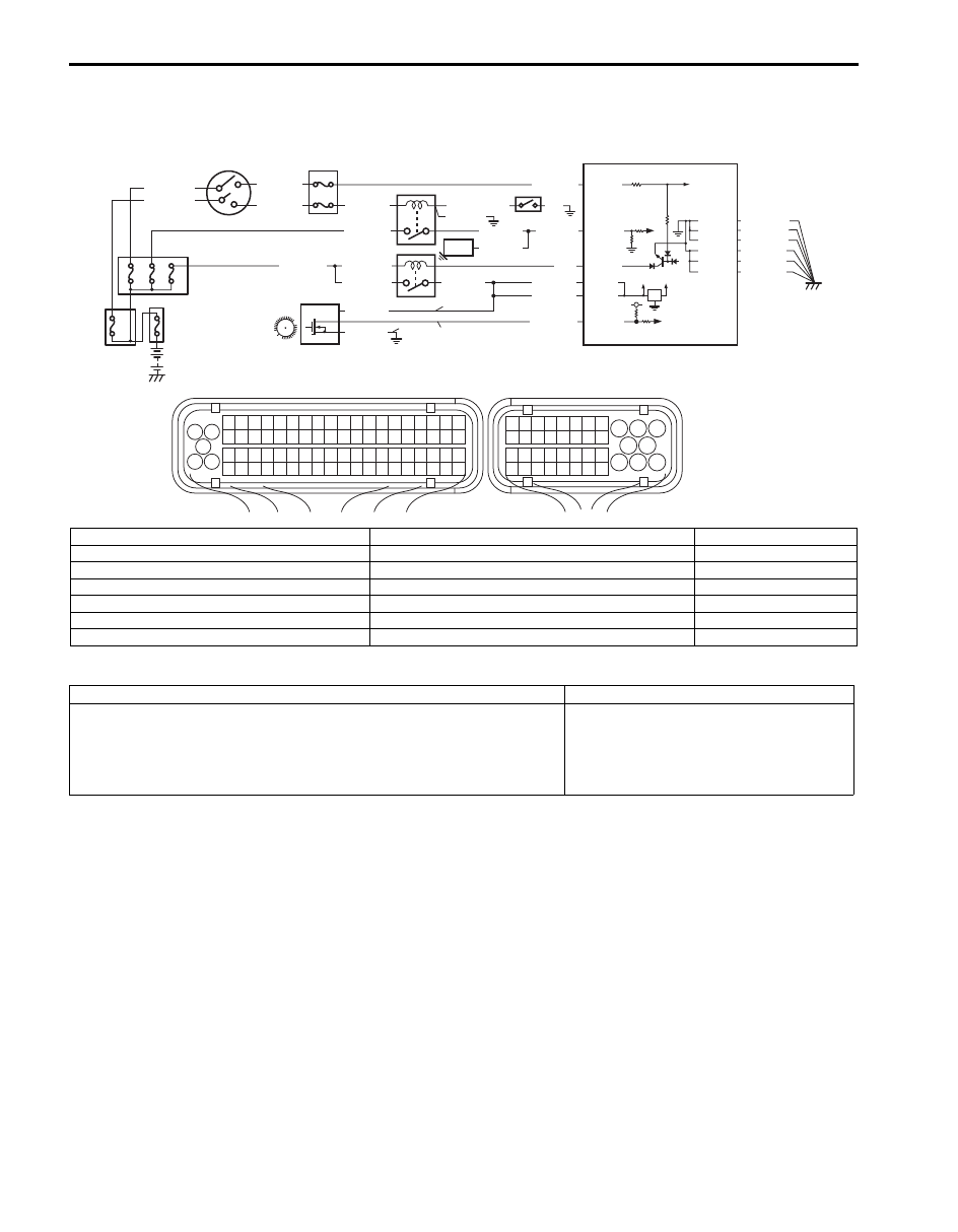
Wiring Diagram
DTC Detecting Condition and Trouble Area
DTC Confirmation Procedure
1) With ignition switch OFF, connect scan tool.
2) Turn ON ignition switch and clear DTC by using scan tool if any.
3) Start engine and run it for 10 sec.
4) Check DTC by using scan tool.
1
3 2
4
5
6
7
8
9
1110
12
13
14
15
16
17
18
19
20
17
18
19
20
21
22
23
24
25
26
27
28
29
30
31
33
34
35
36
37
38
39
40
32
1
2
3
4
5
6
7
8
9
10
11
12
13
14
15
16
21
22
23
24
25
26
27
28
29
30
31
32
33
34
35
36
37
38
39
40
41
42
43
44
45
46
47
48
49
50
51
52
53
54
55
56
57
58
59
60
61
62
63
64
65
66
67
68
69
70
71
72
73
74
75
76
77
78
79
80
81
E23
C37
C37-59
C37-58
C37-39
C37-73
C37-80
BLK/YEL
BLK/ORN
BLK/ORN
BLK/YEL
BLK/YEL
BLK/ORN
C37-81
12V 5V
BLU/BLK
BLU/BLK
BLK/RED
BLK/RED
BLK/RED
BLU
E23-29
E23-2
E23-3
E23-16
BLK/YEL
BLK/YEL
BLK/YEL
BLK/WHT
BLK/YEL
BLK/YEL
BLK/YEL
[A]: BLK/RED
WHT/RED
BLK/RED
BLK
BLU/BLK
C37-28
[B]: BLK
WHT/GRN
BLK/YEL
WHT/BLU
BLU/BLK
C37-47
5
9
14
11 10
2
1
P
G
S
6
8
3
7
4
13
12
I6JB01110036-02
[A]: For A/T model
3. ECM
10. “FI” fuse
[B]: For M/T model
4. Main relay
11. “ST” fuse
P: CKP sensor power supply circuit
5. Ignition switch
12. “ST SIG” fuse
S: CKP sensor signal circuit
6. Starting motor
13. “IG COIL” fuse
G: CKP sensor ground circuit
7. Starting motor control relay
14. “IGN” fuse
1. CKP sensor
8. Transmission range switch (A/T model)
2. Sensor plate on crankshaft
9. Fuse box No.2
DTC detecting condition
Trouble area
CKP sensor outputs signal of less than 15 pulses even through starting
motor switch signal is inputted for more than 3 sec. continuously or CKP
sensor outputs signal of less than 3 pulses for more than 0.2 sec.
continuously within 2 pulses of CMP sensor signal.
(1 driving cycle detection logic)
• CKP sensor and its circuit
• CMP sensor and its circuit
• ECM

Engine General Information and Diagnosis: 1A-118
DTC Troubleshooting
NOTE
Before this trouble shooting is performed, read the precautions for DTC troubleshooting referring to
“Precautions for DTC Troubleshooting”.
Step
Action
Yes
No
1
Was “Engine and Emission Control System Check”
performed?
Go to Step 2.
Go to “Engine and
Emission Control
System Check”.
2
CKP sensor and connector for proper installation check
Is CKP sensor installed properly and connector connected
securely?
Go to Step 3.
Correct.
3
CKP sensor power supply voltage check
1) Disconnect connector from CKP sensor with ignition
switch turned OFF.
2) Check for proper terminal connection to CKP sensor and
ECM connectors.
3) If connections are OK, turn ignition switch to ON
position.
4) Check that CKP sensor power supply voltage is battery
voltage between CKP sensor connector and vehicle
body ground.
Is it in good condition?
Go to Step 4.
Repair or replace CKP
sensor power supply
circuit.
4
Wire harness check
1) Turn ignition switch OFF position.
2) Disconnect connector from ECM.
3) Check that CKP sensor circuit is as follows.
• Wiring harness resistance of CKP sensor signal circuit
is less than 3
Ω.
• Insulation resistance of each CKP sensor signal and
ground circuit between CKP sensor connector and
vehicle body ground is infinity.
• Insulation resistance of wire harness is infinity
between CKP sensor signal terminal and each other
terminal at CKP sensor connector.
• Circuit voltage of each CKP sensor signal circuit and
ground circuit is 0 – 1 V with ignition switch turned
ON.
Are they in good condition?
Go to Step 5.
Repair or replace
defective wire harness.
5
CKP sensor signal circuit voltage check
1) Check that CKP sensor signal circuit voltage is 5 V
between CKP sensor connector and vehicle body
ground.
Is it in good condition?
Go to Step 6.
Substitute a known
good ECM and recheck.
6
CKP sensor check
1) Check CKP sensor and sensor rotor referring to
“Camshaft Position (CMP) Sensor and Crankshaft
Position (CKP) Sensor Inspection in Section 1C”.
Are they in good condition?
Go to Step 7.
Replace CKP sensor
and/or sensor rotor.

1A-119 Engine General Information and Diagnosis:
DTC P0336: Crankshaft Position Sensor Circuit Range / Performance
S6JB0B1104040
Wiring Diagram
Refer to “DTC P0335: Crankshaft Position Sensor Circuit”.
DTC Detecting Condition and Trouble Area
DTC Confirmation Procedure
1) With ignition switch OFF, connect scan tool.
2) Turn ON ignition switch and clear DTC by using scan tool if any.
3) Start engine and it for 10 seconds.
4) Check DTC by using scan tool.
DTC Troubleshooting
7
CMP sensor and its circuit check
1) Check CMP sensor and its circuit referring to Step 2 to 6
of “DTC P0340: Camshaft Position Sensor Circuit”.
Are they in good condition?
Substitute a known
good ECM and recheck.
Repair or replace.
Step
Action
Yes
No
DTC detecting condition
Trouble area
CKP sensor outputs signal of less than 10 pulses for continuous 3 times within
CKP no-teeth reference signal (120
° crank angle).
• CKP sensor and/or sensor rotor
• ECM
Step
Action
Yes
No
1
Was “Engine and Emission Control System Check”
performed?
Go to Step 2.
Go to “Engine and
Emission Control
System Check”.
2
CKP sensor and connector for proper installation check
1) Turn ignition switch to OFF position.
2) Check for proper terminal connection to CKP sensor and
ECM connectors.
3) If connections are OK, check CKP sensor for installation
condition.
Is CKP sensor installed properly?
Go to Step 3.
Repair.
3
CKP sensor check
1) Check CKP sensor and sensor rotor referring to
“Camshaft Position (CMP) Sensor and Crankshaft
Position (CKP) Sensor Inspection in Section 1C”.
Are they in good condition?
Substitute a known
good ECM and recheck.
Replace CKP sensor
and/or sensor rotor.
Engine General Information and Diagnosis: 1A-120
DTC P0340: Camshaft Position Sensor Circuit
S6JB0B1104041
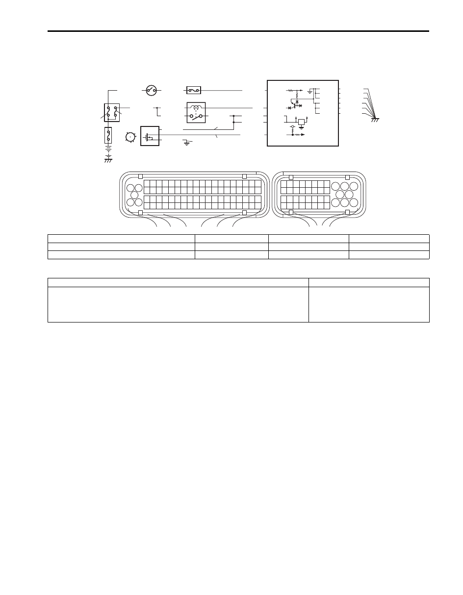
Wiring Diagram
DTC Detecting Condition and Trouble Area
DTC Confirmation Procedure
1) With ignition switch OFF, connect scan tool.
2) Turn ON ignition switch and clear DTC by using scan tool if any.
3) Crank engine for 10 sec.
4) Check DTC by using scan tool.
1
3 2
4
5
6
7
8
9
1110
12
13
14
15
16
17
18
19
20
17
18
19
20
21
22
23
24
25
26
27
28
29
30
31
33
34
35
36
37
38
39
40
32
1
2
3
4
5
6
7
8
9
10
11
12
13
14
15
16
21
22
23
24
25
26
27
28
29
30
31
32
33
34
35
36
37
38
39
40
41
42
43
44
45
46
47
48
49
50
51
52
53
54
55
56
57
58
59
60
61
62
63
64
65
66
67
68
69
70
71
72
73
74
75
76
77
78
79
80
81
E23
C37
C37-59
C37-58
C37-39
C37-73
C37-80
BLK/YEL
BLK/ORN
BLK/ORN
BLK/YEL
BLK/YEL
BLK/ORN
C37-81
12V 5V
BLU/BLK
BLU/BLK
BLK/RED
BLK/RED
BLK/RED
BLU
E23-29
E23-2
E23-3
E23-16
BLK/YEL
BLK/WHT
BLU/BLK
WHT/GRN
BLK/YEL
WHT/RED
BLU/BLK
C37-66
9
6
7
2
1
5
8
3
4
G
S
P
I6JB01110037-03
P: CMP sensor power supply circuit
1. CMP sensor
4. Main relay
7. “FI” fuse
S: CMP sensor signal circuit
2. Signal sensor
5. Ignition switch
8. “IG COIL” fuse
G: CMP sensor ground circuit
3. ECM
6. Fuse box No.2
9. “IGN” fuse
DTC detecting condition
Trouble area
CMP sensor outputs signal of less than 3 pulses even through starting motor
switch signal is inputted for more than 3 sec. continuously, or CKP no-teeth
reference signal (120
° crank angle).
(1 driving cycle detection logic)
• CMP sensor and its circuit
• CKP sensor and its circuit
• ECM
Нет комментариевНе стесняйтесь поделиться с нами вашим ценным мнением.
Текст