Kia Carnival (2007 year). Manual — part 232
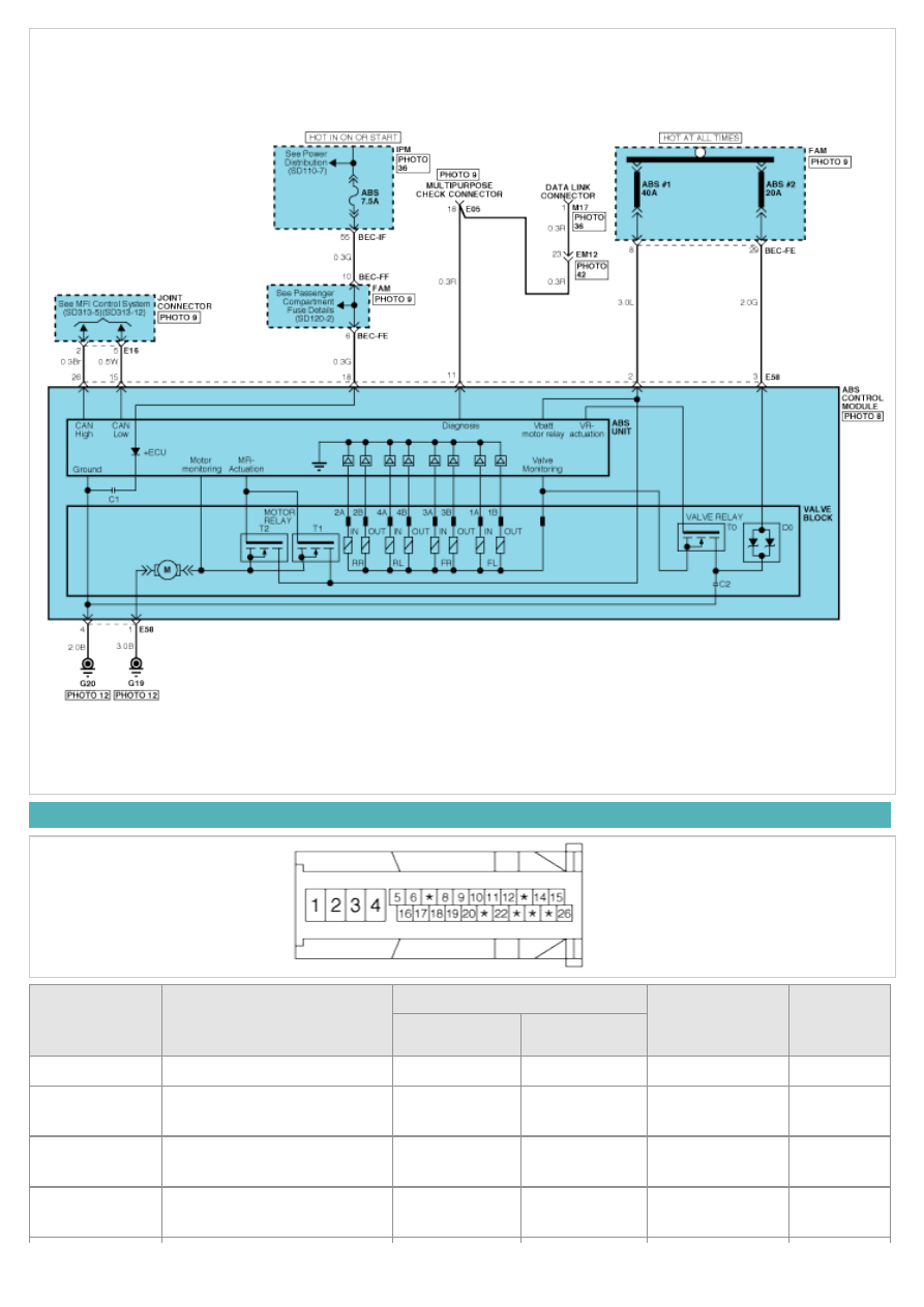
ECU CONNECTOR INPUT/OUTPUT(ABS)
Wire No.
Designation
Current
max.permissible
wire resistance
R_L (m
Ω)
min.leakage
resistance
R_P (k
Ω)
max
min
1
Ground for recirculation pump
20~39 A
10 A
10
4
Ground for solenoid valves
and ECU
5~15 A
2.5 A
10
2
Voltage supply for pump
motor
20~39 A
10 A
10
200
3
Voltage supply for solenoid
valves
5~15 A
2 A
10
200
18
Voltage for hybrid ECU
1 A
500 mA
60
200
5,10,17,19
signal wheel speed sensor FL,
FR, RL,RR
6 mA
16 mA
250
200 to
ground 1.5M
to bat
16,9,6,8
Voltage supply for the active
wheel speed sensor FL,FR,
RL, RR
6 mA
16 mA
250
200 to
ground 1.5M
to bat
14,24
wheel speed sensor output
(FR, RL)
20 mA
10 mA
250
200
11
Diagnostic wire K
6 mA
3 mA
250
200
22
ABS-warning lamp actuation
30 mA
5 mA
250
200
12
EBD-warning lamp actuation
30 mA
5 mA
250
200
20
brake light switch
10 mA
5 mA
250
200
15
CAN Low
30 mA
20 mA
250
200
26
CAN High
30 mA
20 mA
250
200
ABS HECU CONNECTOR
Connector terminal
Specification
Condition
Number
Description
1
Ground for recirculation pump
Current range: Min.10A
Max.20~39A
Always
4
Ground for solenoid valves and
ECU
Current range: Min.2.5A
Max.5~15A
Always
2
Voltage supply for pump motor
Battery voltage
Always
3
Voltage supply for solenoid valves
16
Voltage supply for the active
wheel speed sensor FL,FR, RL,
RR
Battery voltage
IG ON
9
6
8
5
signal wheel speed sensor FL,
FR, RL,RR
Voltage(High) : 0.89~1.26 V
Voltage (Low) : 0.44~0.63 V
On driving
10
17
19
11
Diagnostic wire K
Voltage (High)
≥ 0.8 * IG ON
Voltage (Low)
≤ 0.2 * IG ON
On SCAN TOOL
communication
18
Voltage for hybrid ECU
Battery voltage
KEY ON/OFF
20
Brake light switch
Voltage (High)
≥ 0.8 * IG ON
Voltage (Low)
≤ 0.3 * IG ON
BRAKE ON/OFF
SENSOR OUTPUT ON SCAN TOOL(ABS)
Description
Abbreviation
Unit
Remarks
1
Vehicle speed sensor
VEH. SPD
Km/h
2
Battery voltage
BATT. VOL
V
3
FL Wheel speed sensor
FL WHEEL
Km/h
4
FR Wheel speed sensor
FR WHEEL
Km/h
5
RL Wheel speed sensor
RL WHEEL
Km/h
6
RR Wheel speed sensor
RR WHEEL
Km/h
7
ABS Warning lamp
ABS LAMP
-
8
EBD Warning lamp
EBD LAMP
-
9
Brake Lamp
B/LAMP
-
10
Pump relay state
PUMP RLY
-
11
Valve relay state
VALVE RLY
-
12
Motor
MOTOR
-
13
Front Left valve(IN)
FL INLET
-
14
Front Right valve (IN)
FR INLET
-
15
Rear Left valve (IN)
RL INLET
-
16
Rear Right valve (IN)
RR INLET
-
17
Front Left valve (OUT)
FL OUTLET
-
18
Front Right valve (OUT)
FR OUTLET
-
19
Rear Left valve(OUT)
RL OUTLET
-
20
Rear Right valve (OUT)
RR OUTLET
-
2007 > 2.7L V6 GASOLINE >
DESCRIPTION
This specification applies to HCU(Hydraulic Control Unit) and ECU(Electronic Control Unit) of the HECU.(Hydraulic and
Electronic Control Unit)
This specification is for the wiring design and installation of ABS/TCS/ESC ECU.
This unit has the functions as follows.
a. Input of signal from Pressure sensor, Steering angle sensor, Yaw & Lateral G sensor, the wheel speed sensors
attached to each wheel.
b. Control of braking force / traction force/ yaw moment.
c. Failsafe function.
d. Self diagnosis function.
e. Interface with the external diagnosis tester.
Installation position : engine compartment
a. Brake tube length from Master cylinder port to HECU inlet port should be max. 1m
b. The position should not be close to the engine block and not lower than the wheel.
OPERATION
The ECU shall be put into operation by switching on the operating voltage (IGN).
On completion of the initialization phase, the ECU shall be ready for operation.
In the operating condition, the ECU shall be ready, within the specified limits (voltage and temperature), to process the
signals offered by the various sensors and switches in accordance with the control algorithm defined by the software
and to control the hydraulic and electrical actuators.
Wheel Sensor signal processing
The ECU shall receive wheel speed signal from the four active wheel sensors.
The wheel signals are converted to voltage signal by the signal conditioning circuit after receiving current signal from
active wheel sensors and given as input to the MCU.
Solenoid Valve Control
When one side of the valve coil is connected to the positive voltage that is provided through the valve relay and the
other side is connected to the ground by the semiconductor circuit, the solenoid valve goes into operation.
The electrical function of the coils are always monitored by the valve test pulse under normal operation conditions.
Voltage limits
a. Overvoltage
When overvoltage is detected(above 16.8 V), the ECU switches off the valve relay and shuts down the system.
When voltage is returned to operating range, the system goes back to the normal condition after the initialization
phase.
b. Undervoltage
In the event of undervoltage(below 9.3 V), ABS control shall be inhibited and the warning lamp shall be turned on.
When voltage is returned to operating range, the warning lamp is switched off and ECU returns to normal operating
mode.
Pump Motor Checking
The ECU performs a pump motor test at a speed of 15km/h once after IGN is switched on.
Diagnostic Interface
Failures detected by the ECU are encoded on the ECU, stored in a EEPROM and read out by diagnostic equipment
when the ignition switch is turned on.
The diagnosis interface can also be used for testing the ECU during production of the ECU and for actuating the HCU
(Air-bleeding line or Roll and Brake Test line).
Warning Lamp module
Нет комментариевНе стесняйтесь поделиться с нами вашим ценным мнением.
Текст