Kia Carnival (2007 year). Manual — part 92
13
OIL TEMPERATURE
°C
40°C
Current Oil temperature
80°C
14
SHIFT POSITION
N,P,REV/1st G/…/5th
G
D
Current shift position
P, N
15
SELECT LEVEL
P,N/R/D/SPORTS
D
Current shift lever position
P, N
16
A/CON SWITCH
OFF/ON/-/NOT
SUPP
OFF
-
17
IDLE STATUS
OFF/ON/-/NOT
SUPP
ON
When idling, ON
18
BRAKE SWITCH
OFF/ON/-/NOT
SUPP
ON
When braking, ON
19
AUTO CRUISE
SWITCH
OFF/ON/-/NOT
SUPP
20
AUTO CRUISE
RELEASE
―
―
21
SPORT MODE
SELECT SW
OFF/ON/-/NOT
SUPP
ON
When selecting sport mode, ON
22
SPORT MODE UP SW
OFF/ON/-/NOT
SUPP
ON
When Selecting Sport mode up, ON
23
SPORT MODE DOWN
SW
OFF/ON/-/NOT
SUPP
ON
When selecting sport mode down,
ON
24
A/T CONTROL RELAY
VOLT
V
12.9V
0V
25
ENGINE TORQUE
%
20%
26
HIVEC MODE
A/B/C/D/E/F/G/H/I/J/K
F
A/B/C/D is control mode, F is
release mode
F
HIVEC -SAT(SIEMENS ADAPTIVE TRANSMISSION CONTROL) Mode (Shift Patten)
Shift patten
Description(Help)
SCAN DISPLAY
ECONOMY
Economy Driver shift patten for flat road
A
MEDIUM
Shift patten for medium road
B
SPORTS
Shift patten for sport road
C
LOAD 1
Shift patten for low land, slow grade and slope
D
LOAD 2
Shift patten for low land, steep grade and slope
E
LOAD 3
Shift patten for downhill road
F
LOAD 1 HI ALT
Shift patten for high land, steep grade and slope
G
LOAD 2 HI ALT
Shift patten for low land, steep grade and slope
H
HI TEMP
Shift patten for high temperture ATF
I
WARM UP
Shift patten for exhaust gas decrease
J
HOLD
Shift patten for when hold, switch on
K
Actuator inspection
NO
ITEM NAME
Actuator Driving
Condition
1
LR SOLENOID(SCSV A)
1. IG Key ON
2. Inhibitor SW normal
3. P range
2
UD SOLENOID(SCSV B)
3
2ND SOLENOID(SCSV C)
Solenoid valve driver for 5sec.
3. P range
4. Vehicle speed 0km/h
5. Engine stop
6. No failure
7. TPS < 1V
4
OD SOLENOID(SCSV D)
5
TORQUE CONVERTER SOLENOID VALVE
6
A/T CONTROL RELAY
OFF for 3 sec.
-
7
INTELLIGENT SHIFT PROHIBIT
Prohibit until IG off
-
8
CLEAR LEARNING VALUE
-
-
ROAD TEST
No.
Condition
Operation
Judgment value
Check item
1
Ignition switch : OFF
Ignition switch
(1) ON
Battery voltage (mV)
Control relay
2
a. Ignition switch :
ON
b. Engine : Stopped
c. Selector lever
position : P
Selector lever position
(1) P, (2) R, (3) N, (4) D
(1) P, (2) R, (3) N, (4)
D
Transaxle range switch
Accelerator pedal
(1) Released
(2) Half depressed
(3) Depressed
(1) 400~1,000 mV
(2)Gradually rises
from (1)
(3) 4,500~5,000 mV
Throttle position sensor
Brake pedal
(1) Depressed
(2) Released
(1) ON
(2) OFF
Brake switch
3
a. Ignition switch : ST
b. Engine : Stopped
Starting test with lever P or
N range
Starting should be
possible
Starting possible or
impossible
4
Warming up
Drive for 15 minutes or
more so that the automatic
fluid temperature becomes
70~90°C
Gradually rises to
70~90°C
Oil temperature sensor
5
a. Engine : Idling
b. Selector lever
position : N
A/C switch
(1) ON
(2) OFF
(1) ON
(2) OFF
Triple pressure switch
Accelerator pedal
(1) Released
(2) Half depressed
(1) ON
(2) OFF
Idle position switch
(1) 600~900 rpm
(2) Gradually rises
from (1)
(1) Data changes
Communication with
engine-ECU
Selector lever position
(1) N
→D
(2) N
→R
Should be no
abnormal shifting
shocks
Time lag should be
within 2 seconds
Malfunction when starting
Selector lever position
: N (Carry out on a
flat and straight road)
Selector lever position and
vehicle speed
a. Idling in 1st gear
(Vehicle stopped)
b. Driving at constant
speed of 20 km/h in 1st
gear
(2) 1st, (4) 3rd, (3)
2nd, (5) 4th
Shift condition
(2) 0%, (4) 100%, (3)
100%, (5) 100%
Low and reverse solenoid
valve
(2) 0%, (4) 0%, (3)
0%
Underdrive solenoid valve

6
c. Driving at constant
speed of 30 km/h in 2nd
gear
d. Driving at 50 km/h in 3rd
gear with accelerator
fully closed
e. Driving at constant
speed of 50 km/h in 4th
gear
(1) 100%, (2) 0%, (3)
100%
Second solenoid valve
(2) 100%, (3) 100%,
(4) 0%
Overdrive solenoid valve
(1) 0km/h
(4) 50km/h
Vehicle speed sensor
(4) 1,800 ~ 2,100rpm
Input shaft speed sensor
(4) 1,800 ~ 2,100rpm
Output shaft speed sensor
7
Selector lever position
: D (Carry out on a
flat and straight road)
a. Accelerate to 4th gear at
a throttle position sensor
output of 1.5V
(accelerator opening
angle of 30 %).
b. Gently decelerate to a
standstill.
c. Accelerate to 4th gear at
a throttle position sensor
output of 2.5 V
(accelerator opening
angle of 50%).
d. While driving at 60 km/h
in 4th gear, shift down
to 3rd gear.
e. While driving at 40 km/h
in 3rd gear, shift down
to 2nd gear.
f. While driving at 20 km/h
in 2nd gear, shift down
to 1st gear.
For (1), (2) and (3),
the reading should be
the same as the
specified output shaft
torque, and no
abnormal shocks
should occur.
For (4), (5) and (6),
downshifting should
occur immediately
after the shifting
operation is made.
Malfunction when shifting
Displaced shift points
Does not shift
Does not shift from 1 to 2 or
2 to 1
Does not shift from 2 to 3 or
3 to 2
Does not shift from 3 to 4 or
4 to 3
8
Selector lever position
: N (Carry out on a
flat and straight road)
Move selector lever to R
range drive at constant
speed of 10km/h
The ratio between
input and output shaft
speed sensor data
should be the same
as the gear ratio
when reversing.
Does not shift
TORQUE CONVERTER STALL TEST
This test measures the maximum engine speed when the selector lever is in the D or R position. The torque converter
stalls to test the operation of the torque converter, starter motor, one-way clutch operation, the holding performance of
the clutches, and brakes in the transaxle.
Do not let anybody stand in front of or behind the vehicle while this test is being carried out
1. Check the automatic transmission fluid level and temperature, and the engine coolant temperature.
a. Fluid level : At the HOT mark on the oil level gauge
b. Fluid temperature : 80~100°C (176~212°F)
c. Engine coolant temperature : 80~100°C(176~212°F)
2. Prevent all the wheels from moving during the test.
3. Pull the parking brake lever up, with the brake pedal fully depressed.
4. Start the engine.
5. Move the selector lever to the "D" position, fully depress the accelerator pedal and take a reading of the maximum
engine speed at this time.
Stall speed : 2,100~2,900rpm
a. The throttle should not be left fully open for any more than five seconds.
b. If carrying out the stall test two or more times, move the selector lever to the "N" position and run the
engine at 1,000 r/min to let the automatic transaxle fluid cool down before carrying out subsequent tests.
6. Move the selector lever to the "R" position and carry out the same test again.
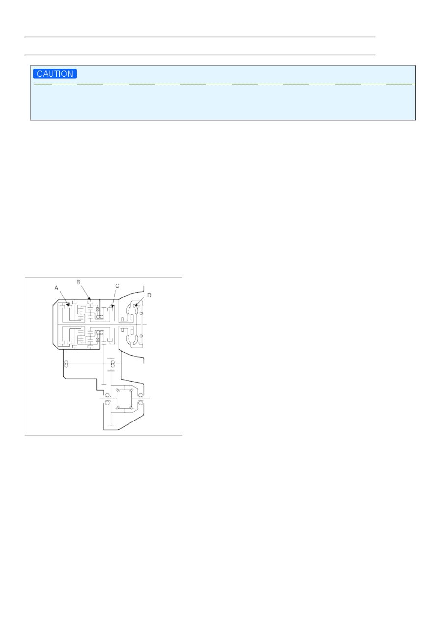
TORQUE CONVERTER STALL TEST CONCLUSION
1. Stall speed is too high in both "D" and "R" ranges
a. Low line pressure
b. Low & reverse brake(B) slippage
2. Stall speed is to high in "D" range only
a. Underdrive clutch(C) slippage
3. Stall speed is too high in "R" range only
a. Reverse clutch(A) slippage
4. Stall speed too low in both "D" and "R" ranges
a. Malfunction of torque converter(D)
b. Insufficient engine output
HYDRAULIC PRESSURE TEST
1. Warm up the engine until the automatic transaxle fluid temperature is 80-100°C.
2. Lift up the vehicle so that the wheels are free to turn.
3. Connect the special tool (oil pressure gauge) to each pressure discharge port.
4. Measure the hydraulic pressure at each port under the conditions given in the standard hydraulic pressure table,
and check that the measured values are within the standard value ranges.
5. If a value is outside the standard range, correct the problem while referring to the hydraulic pressure test diagnosis
table.
Нет комментариевНе стесняйтесь поделиться с нами вашим ценным мнением.
Текст