Kia Carnival (2007 year). Manual — part 89
BRAKES
The gear changing mechanism utilizes two multi-disc brakes.
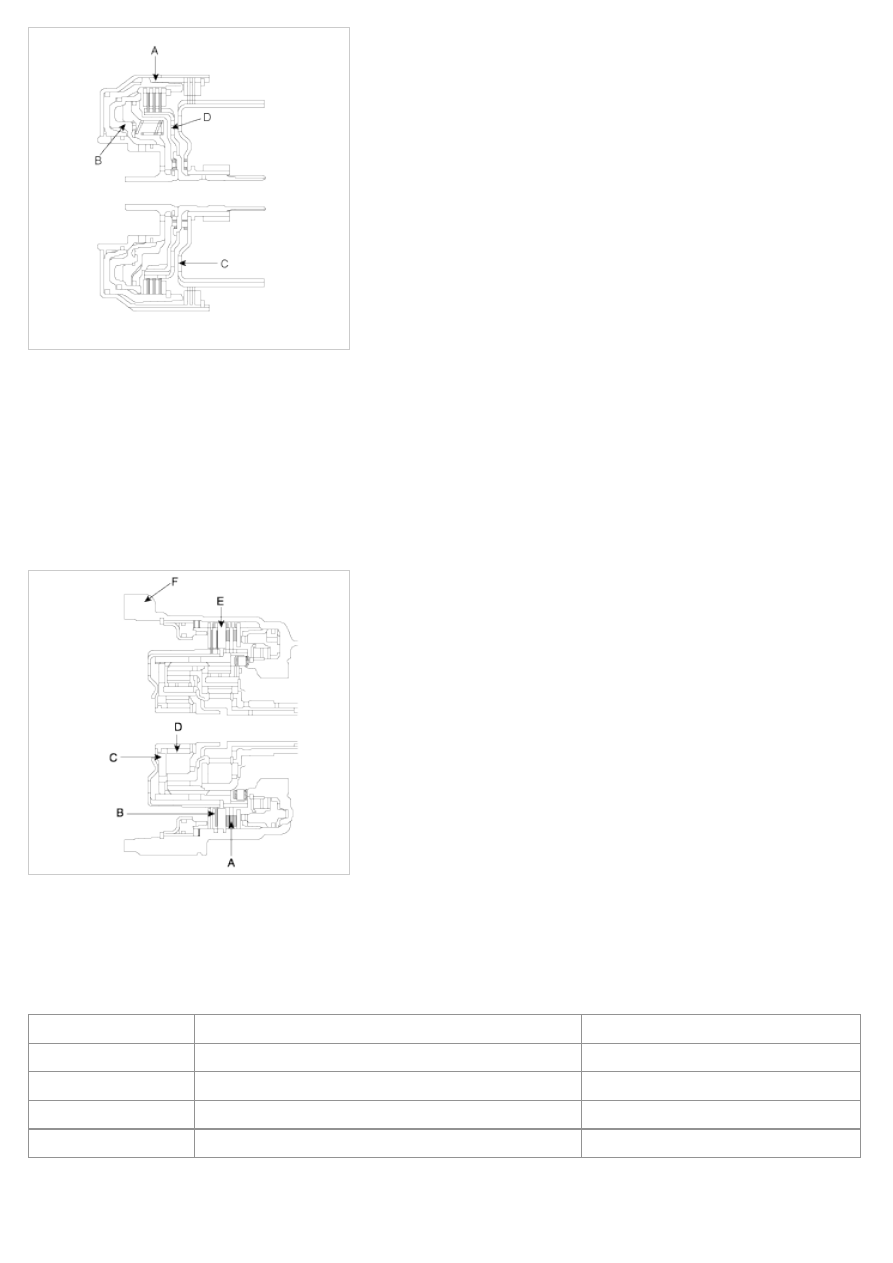
LOW&REVERSE BRAKE AND SECOND BRAKE
The low&reverse brake(A) operates in 1st and reverse gears, when the vehicle is parked, and during manual
operation. It locks the low&reverse annulus gear and overdrive planetary carrier to the case.
The second(C) brake(B) operates in 2nd and 4th gears and locks the reverse sun gear(D) to the case.
The components comprising the low&reverse brake and second brake are as illustrated below.
As shown, the discs and plates of the two brakes are arranged on either side of the rear cushion plate(E), which is
itself secured to the case(F) by a snap ring.
OWC
To improve the shift feeling from 1st to 2nd gear, OWC was adopted on the low&reverse brake annulus gear. Instead
of hydraulic fixing by Low&reverse brake at the 1st gear, this mechanical fixing device was used. This structure is not
a new concept, because this OWC already has been installed on the previous models.
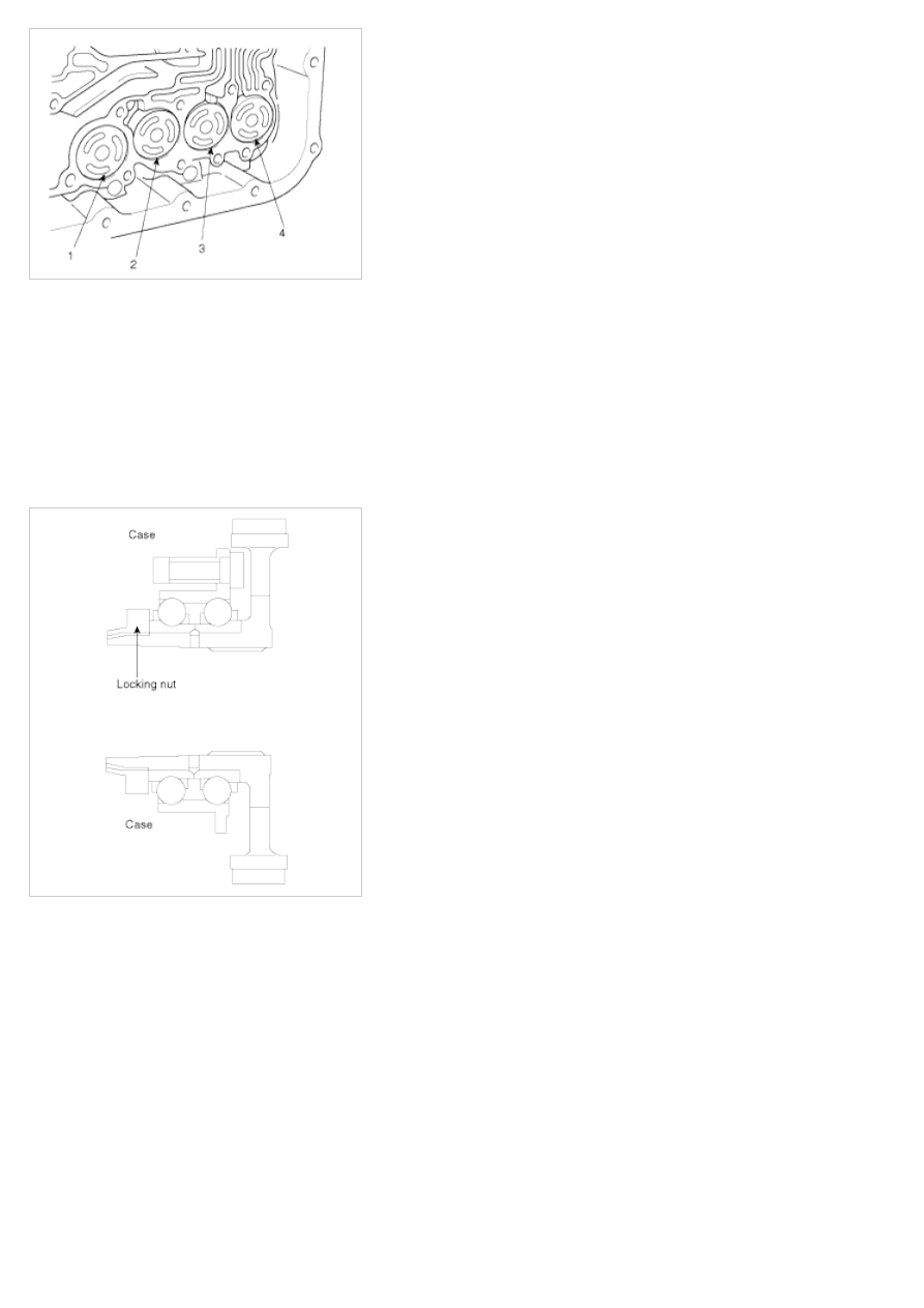
ACCUMULATORS
Number
Function Name
Color
1
Low&Reverse Brake
None
2
Underdrive Clutch
Yellow
3
Second Brake
Blue
4
Overdrive Clutch
None
Objective
* Energy (hydraulic pressure) storage
* Impact and pulsation damping when solenoid valves operating
* Operation as spring element
* Smooth shifting by preventing sudden operation of clutches and brakes
TRANSFER DRIVE GEAR
With the transfer drive gear, increased tooth height and a higher contact ratio have reduced gear noise.
Also, the bearing that supports the drive gear is a preloaded type that eliminates rattle, and the rigidity of the gear
mounting has been increased by bolting the bearing directly onto the case.
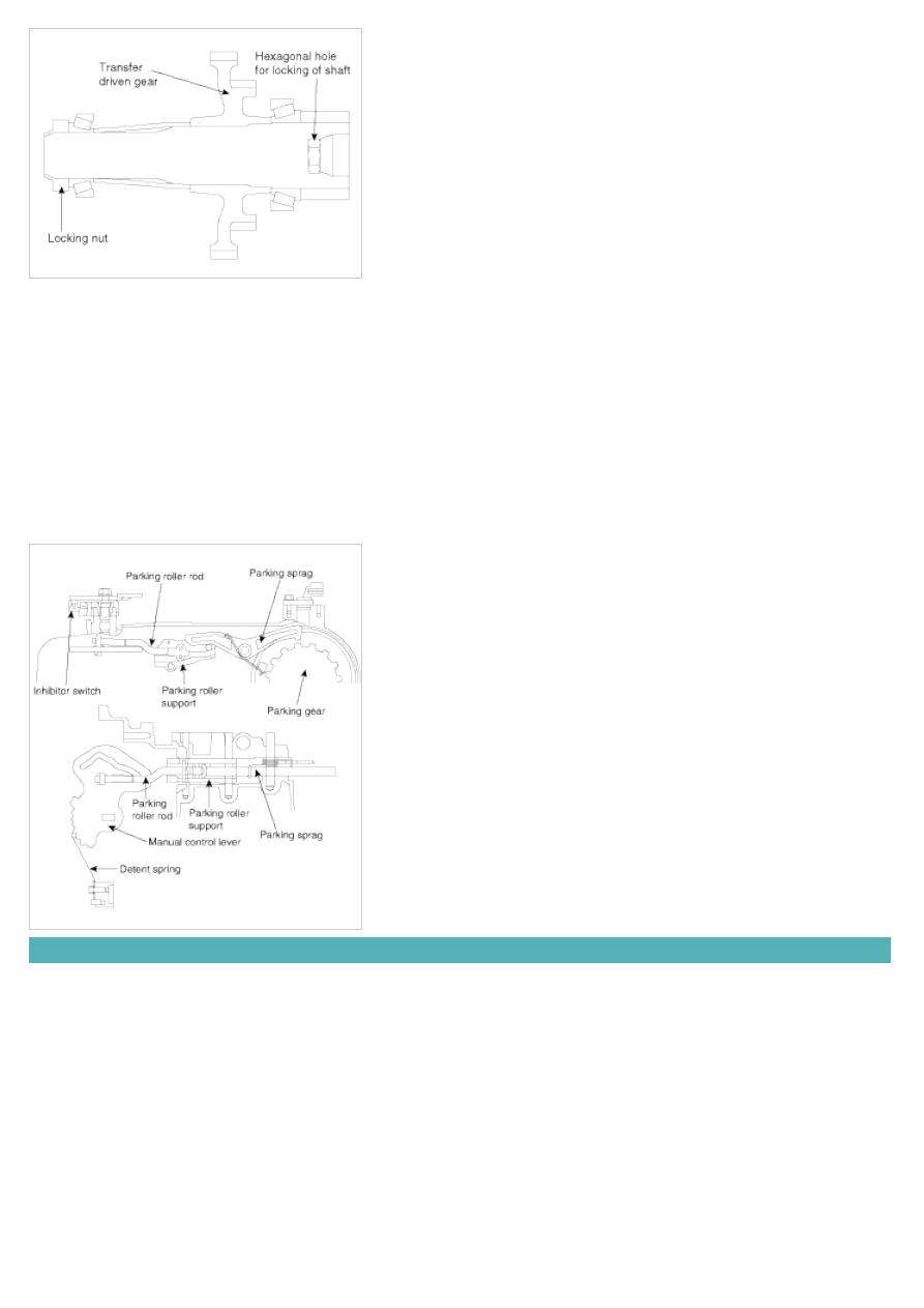
OUTPUT SHAFT/TRANSFER DRIVEN GEAR
As shown in the illustration below, the transfer driven gear is press-fitted onto the output shaft, and the output shaft is
secured by a locking nut and supported by bearings.
The locking nut has a left-handed thread, and a hexagonal hole in the other end of the shaft enables the shaft to be
held in position for locking nut removal.
MANUAL CONTROL SYSTEM
MANUAL CONTROL LEVER
The manual control lever is fitted to the top of the valve body and is linked to the parking roller rod and manual control
valve pin.
A detent mechanism is provided to improve the gear shift feeling during manual selection.
PARKING MECHANISM
When the manual control lever is moved to the parking position, the parking roller rod moves along the parking roller
support and pushes up the parking sprag.
As a result, the parking sprag meshes with the transfer driven gear (parking gear), thereby locking the output shaft. To
minimize the operating force required, a roller is fitted to the end of the rod.
POWER TRAIN
P POSITION
Hydraulic pressure is applied to the LR brake and the RED brake, so power is not transmitted from the input shaft to
the UD clutch or OD clutch, and the output shaft is locked by the park brake pawl interlocking the park gear.
N POSITION
Hydraulic pressure is applied to the LR brake(A) and the RED brake, so power is not transmitted from the input shaft
to the UD clutch or OD clutch.
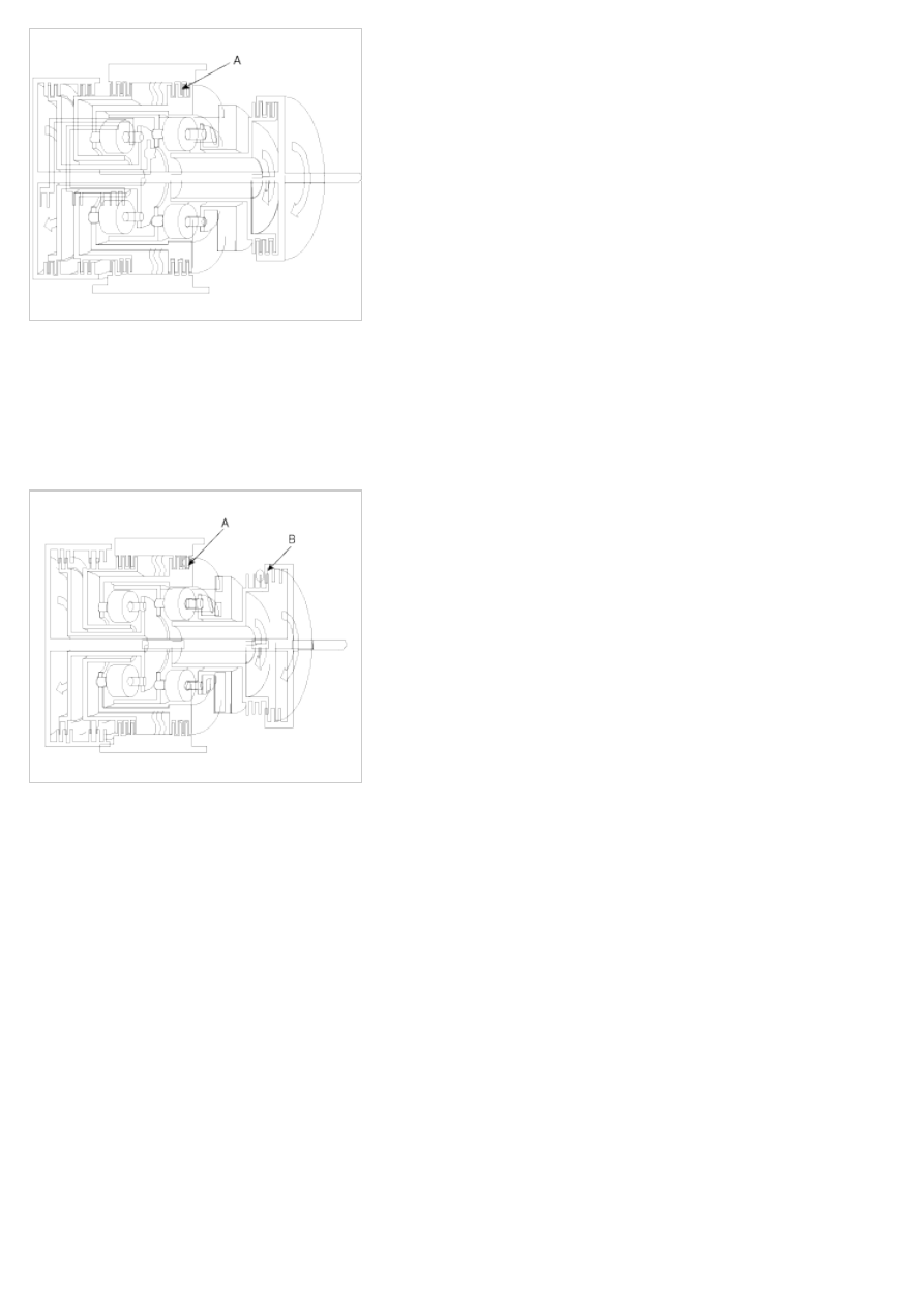
1st GEAR POWER FLOW
Hydraulic pressure is applied to the UD clutch(B) the LR brake(A) and the one way clutch(OWC), then the UD clutch
transmits driving force from the input shaft to the UD sun gear, and the LR brake locks the LR annulus gear to the
case.The UD sun gear of the planetary gear drives the output pinion gear, and the LR brake locks the annulus gear,
and the output pinion drives the output carriers, and the output carrier drives the transfer drive gear, and the transfer
drive gear drives the transfer driven gear of the output shaft, and power is transmitted to the differential gear through
the differential drive gear.
2nd GEAR POWER FLOW
Hydraulic pressure is applied to the UD clutch(A) the 2nd brake(B) and the one way clutch(OWC), then the UD clutch
transmits driving force from the input shaft to the UD sun gear, and the 2nd brake locks the reverse sun gear to the
case.The UD sun gear of the planetary gear drives the output pinion gear and the LR annulus gear, and the LR
annulus gear drives the OD planetary carriers, and OD planetary carriers drives OD pinion gear, and the OD pinion
gear drives the output carriers, and the output carrier drives the transfer drive gear, and the transfer drive gear drives
the transfer driven gear of the output shaft, and power is transmitted to the differential gear through the differential
drive gear.
Нет комментариевНе стесняйтесь поделиться с нами вашим ценным мнением.
Текст