Fiat 500L Living (2022 year). Manual in english — page 3
44
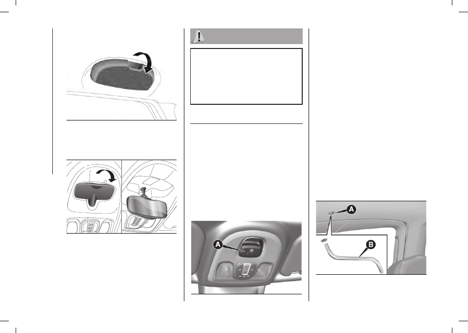
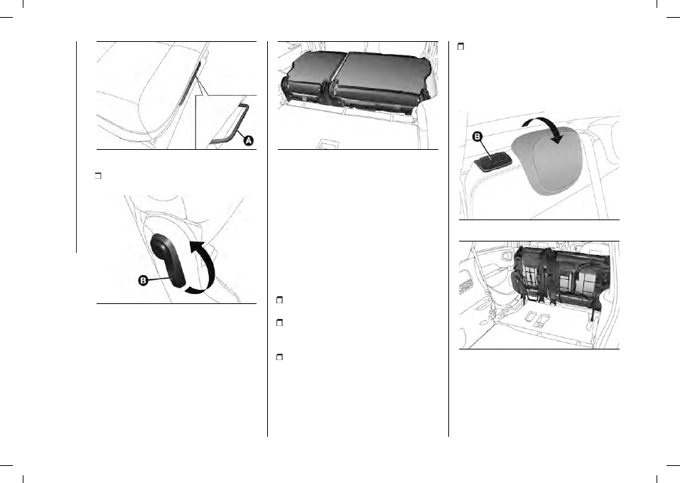
SUNGLASSES HOLDER
(for versions/markets, where provided)
55
F0Y0051
REAR SEAT
SURVEILLANCE MIRROR
(for versions/markets, where provided)
56
F0Y0775
FIRE EXTINGUISHER
(for versions/markets, where provided)
When required, the extinguisher is
located in the boot.
18)
Do not travel with the storage
compartment open: it may injure the
front seat occupants in the event of an
accident.
19)
The cigar lighter gets extremely hot.
Handle it carefully and make sure that
children don’t use it: risk of fire and/or
burns.
FIXED GLASS ROOF
(for versions/markets, where provided)
It comprises an extensive fixed glass
panel and is fitted with an electrically
operated sunshade.
SUNSHADE MOVEMENT
The sunshade operates only with the
ignition key turned to MAR. From the
fully closed position, press button (A)
fig. 57 for more than half a second: the
sunshade will move to the fully open
position.
57
F0Y0121C
From the fully open position, press
button (A) for more than half a second:
the sunshade will move to the fully
closed position.
Button (A) can be pressed in jog
mode to open or close the sunshade
manually.
Press (A) again during automatic
opening and closing to stop the
sunshade movement.
EMERGENCY OPERATION
If the control button does not work, to
move the sunshade manually, remove
the protective cap (A) fig. 58 on the
internal trim, take the hex wrench
B provided (located in the tool box
or, depending on the version, in the
Fix&Go Automatic container in the
boot), insert it in housing A and turn
it clockwise to open the blind or
anticlockwise to close it.
58
F0Y0285C
-------------------------------------------------------------------------------------------------------------------------------------------------------------
45
SUNSHADE
INITIALISATION
PROCEDURE
Following an automatic movement
malfunction while opening/closing or
after an emergency manoeuvre (see
description in the previous paragraph),
the automatic operation of the
sunshade must be initialised again.
Proceed as follows:
turn the ignition key from the STOP
position to the MAR position;
hold down button (A) fig. 57: after
approximately 10 seconds the
sunshade moves jerkily to closing
position. When the movement stops
(sunshade closed), release button (A) (if
the sunshade is already closed, you will
hear the mechanical lock only);
press button (A) again within 3
seconds after the blind reached the
fully closed position;
hold down button (A): the sunshade
will perform an automatic opening
and closing cycle. Should this not
occur, repeat the operation from the
beginning;
hold down button (A) until the
sunshade is completely closed: the
initialisation procedure has ended.
ELECTRIC SUNROOF
(for versions/markets, where provided)
20)
9)
The sunroof and the sunshade can
be operated only with the ignition key
turned to MAR.
CONTROL BUTTONS
Opening/closing the front glass
panel
Opening
Press button (A) fig. 59 to open the
sunroof in the “spoiler” position. After
opening in spoiler position, press
button (A) once again for more than half
a second to bring the roof automatically
to fully open position. To deactivate the
automatic movement press the button
again. Use button (A) in jog mode to
open the sunroof manually.
Closing
From the fully open position press
button (A) for more than half a second:
the front glass panel will move into the
“spoiler” position.
Use button (A) in jog mode to close the
sunroof manually.
59
F0Y0120C
Sunshade movement
Pressing the (B) fig. 59 button will move
the sunshade towards the rear part
of the car, until it is fully open. With
sunshade fully open press button B:
the sunshade will move towards the
front part of the car, until it is fully
closed.
During the sunshade automatic
opening and closing stages, press
the button again to interrupt the blind
movement.
Button (B) can be pressed in jog
mode to open or close the sunshade
manually.
EMERGENCY OPERATION
If the control buttons fail to operate,
the sunshade and the sunroof can
be moved manually proceeding as
described below:
-------------------------------------------------------------------------------------------------------------------------------------------------------------
46
Sunshade movement:
remove
protective cap(A) fig. 60 on the internal
trim;
Sunroof movement:
remove
protective cap (B) on the internal trim;
60
F0Y0234C
take the hex wrench (C) fig. 60
provided (located in the tool box or,
depending on the version, in the
Fix&Go Automatic container), insert it in
socket (A) (to operate the sunshade) or
(B) (to operate the sunroof) and turn
it clockwise to open the sunroof (or
sunshade) or anticlockwise to close it.
SUNROOF
INITIALISATION
PROCEDURE
Following an automatic movement
malfunction while opening/closing or
after an emergency manoeuvre (see
description in the previous paragraph),
the automatic operation of the sunroof
must be initialised again.
Proceed as follows
turn the ignition key from the STOP
position to the MAR position;
hold down button (A) fig. 59: after
approximately 10 seconds the roof
moves jerkily to closing position. When
the movement stops (closed roof),
release button (A) (if the roof is already
closed, you will hear the mechanical
lock only);
press button (A) again within 5
seconds after the blind reached the
fully closed position;
hold down button (A): the roof
will perform an automatic opening
and closing cycle. Should this not
occur, repeat the operation from the
beginning;
hold down button (A) until the roof
is completely closed: the initialisation
procedure has ended.
20)
When leaving the vehicle, always
remove the key from the ignition to avoid
the risk of injury to those still inside the
vehicle due to accidental operation of the
sun roof. Improper use of the roof can be
dangerous. Before and during operation,
always check that no-one is exposed to
the risk of being injured by the moving
sunroof or by objects getting caught or hit
by it.
9)
Do not open the sunroof if a transverse
roof rack is fitted. Do not open the sunroof
if there is snow or ice on it: you may
damage it.
DOORS
DOOR CENTRAL
LOCKING/UNLOCKING
Locking from the outside
With doors closed, press the
button
on the remote control or turn the metal
insert (located inside the key) in the
driver side door lock. Door locking
is carried out with all doors shut,
irrespective of the boot open/closed
status.
Door unlocking from the outside
Press button
on the remote control
or turn the metal insert (located inside
the key) in the driver side door lock.
Door locking/unlocking from the
inside
Press button
on the dashboard
fig. 61.
LED on button on:
doors locked /
LED on button off
: doors unlocked.
-------------------------------------------------------------------------------------------------------------------------------------------------------------
47
61
F0Y0652C
WARNING With central locking active,
pulling the internal opening lever of the
passenger side door unlocks the door
(the LED stays on). Pulling the internal
opening lever of the driver side door
activates central unlocking.
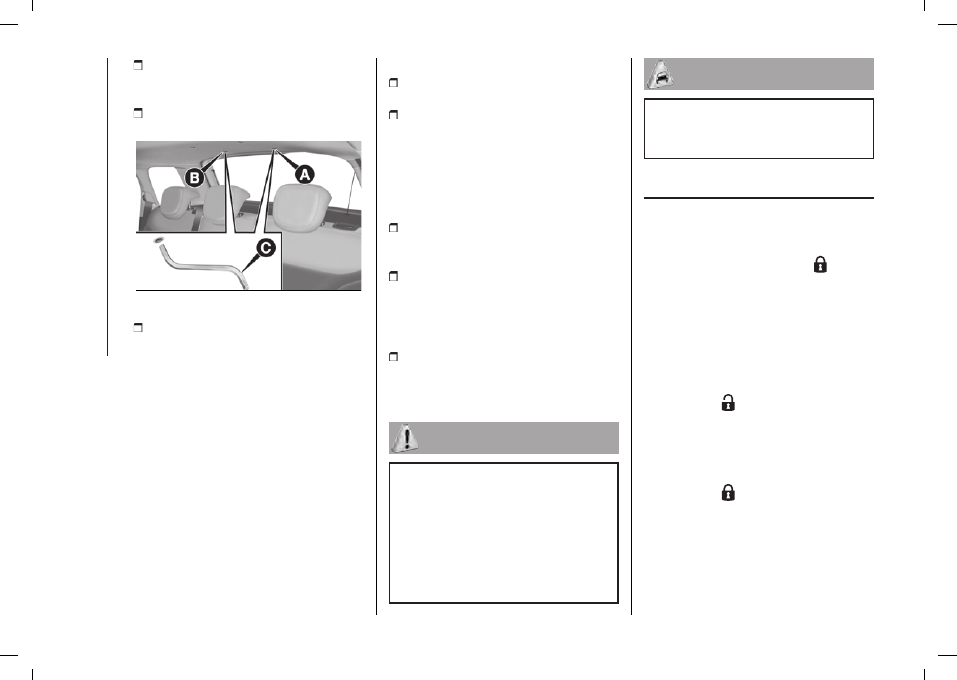
CHILD LOCK
21)
This system prevents the rear doors
from being opened from the inside.
This device (B) fig. 62 can be engaged
only with the doors open.
Position 1
: device on (door locked)
/
Position 2
: device off (door can be
opened from the inside). The device
remains engaged even if the doors are
electrically unlocked.
62
F0Y0111C
WARNING The rear doors cannot be
opened from the inside when the child
lock is engaged.
PASSENGER SIDE
FRONT DOOR AND REAR
DOOR EMERGENCY
LOCKING DEVICE
10)
Used to lock the doors when there is
no electrical power supply. Insert the
metal insert of the ignition key into slot
(A) fig. 63 (front door on passenger
side) or slot (A) fig. 62 (rear doors)
and then turn the key clockwise and
remove it from slot (A).
63
F0Y0110C
To restore the starting condition of
the door locks (only if battery charge
restored) press the
button on the
remote control or the
button on the
dashboard or introduce the metal insert
of the ignition key in the driver's side
front door pawl and pull the door inner
handle.
INITIALISING THE DOOR
OPENING / CLOSING
MECHANISM
If the battery is disconnected or
the protection fuse blows, the door
opening/closing mechanism must be
initialised as follows:
close all the doors;
-------------------------------------------------------------------------------------------------------------------------------------------------------------
48
press the
button on the remote
control or the button on the dashboard;
press the
button on the remote
control or the button on the dashboard;
21)
Always use this device when carrying
children. After engaging the device on
both rear doors, check that it is actually
engaged by trying to open a door with the
internal handle.
10)
If the child lock was engaged and the
previously described locking procedure
carried out, operating the internal opening
handle will not open the door: in this
case, to open the door, the outside
handle must be used. The door central
locking/unlocking button
is not disabled
by the engagement of the emergency lock.
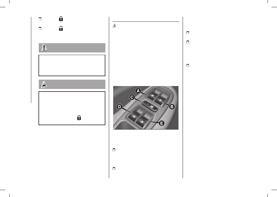
ELECTRIC WINDOWS
22)
OPERATION
These operate when the ignition key
is turned to MAR-ON and for about 3
minutes after the ignition key is turned
to STOP or removed unless one of the
front doors is opened.
DRIVE SIDE FRONT
DOOR CONTROLS
Versions with 4 electric windows
The buttons are located on the door
panel trim fig. 64.
64
F0Y0240C
All windows can be controlled from the
driver side door panel.
A:
front left window opening/closing.
“Automatic continuous" operation
during window opening/closing stage
and anti-pinch system activated.
B:
right front window
opening/closing. "Automatic
continuous" operation during window
opening/closing and anti-pinch system
activated.
C:
enabling/disabling of rear door
electric window controls.
D:
rear left window opening/closing
(for versions/markets, where provided).
“Automatic continuous" operation
during window opening/closing stage
and anti-pinch system activated.
E:
rear right window opening/closing
(for versions/markets, where provided).
"Automatic continuous" operation
during window opening/closing and
anti-pinch system activated.
Anti-crush safety device
(for versions/markets, where provided)
The anti-pinch function is active both
during manual and automatic operation
of the electric windows.
When the anti-crush system is
activated the window travel is
immediately interrupted and then
reversed. The window cannot be
operated in any way during this time.
WARNING If the anti-crush protection
intervenes 3 consecutive times within
1 minute or is faulty, the automatic
closing operation of the window is
inhibited, only allowing it in steps of half
a second; the button is released for
the subsequent manoeuvre. In order
-------------------------------------------------------------------------------------------------------------------------------------------------------------
49
to restore the correct operation of the
system, the relevant window must be
lowered.
Remote window opening/closing
using a key with remote control.
(for versions/markets, where provided)
The windows can be opened/closed
by holding the unlock ( ) / lock ( )
buttons on the key with remote control
pressed, respectively.
The windows move simultaneously as
long as the corresponding button is
held down; they will stop when they
reach the upper or lower end of travel
position, or the button is released.
ELECTRIC WINDOWS
INITIALIZATION
If power supply is interrupted when
the window is moving, the electric
window automatic operation must be
reinitialised. The initialisation procedure
must be carried out with the doors
closed (and for each door) as follows:
fully close the window to be
initialised, with manual operation;
after the window has reached the
upper end of travel, hold the up button
pressed for at least one second.
22)
Improper use of the electric windows
can be dangerous. Before and during
operation, always check that passengers
are not exposed to the risk of being injured
either directly by the moving windows or
through objects getting caught or struck
by them. When leaving the vehicle, always
remove the ignition key to avoid the risk
of injury for people still on board due
to accidental operation of the electric
windows.
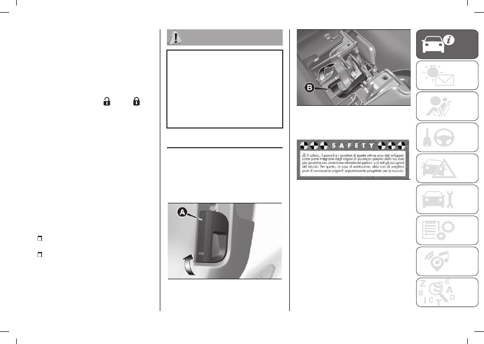
BONNET
OPENING
Pull the lever (A) fig. 65 in the direction
indicated by the arrow and then
operate the lever (B) fig. 66 operating in
the direction shown by the arrow. Then
lift the bonnet.
65
F0Y0611C
66
F0Y0115C
The following plate is applied inside the
engine compartment fig. 67.
67
F0Y1100C
WARNING Two side gas shock
absorbers are provided to assist in
opening the bonnet. Do not tamper
with these shock absorbers and
accompany the bonnet when raising.
WARNING Before raising the bonnet,
make sure that the arms of the wipers
are not raised from the windscreen and
that the wiper is not operational.
-------------------------------------------------------------------------------------------------------------------------------------------------------------
50
CLOSING
23)
Lower the bonnet to approximately
20 centimetres from the engine
compartment then let it drop. Make
sure that the bonnet is completely
closed and not only fastened by the
locking device by trying to open it.
If it is not perfectly closed, do not try to
press the bonnet lid down but open it
and repeat the procedure.
23)
For safety reasons, the bonnet must
always be properly closed while driving.
Therefore, make sure that the bonnet
is properly closed and that the lock is
engaged. If you discover that the bonnet
is not perfectly closed while driving, stop
immediately and close the bonnet in the
correct manner.
BOOT
24) 25) 26)
11)
The boot unlocking is electrically
operated and is deactivated when the
car is in motion.
WARNING When travelling, do not
put any object on the rear parcel shelf
because they can injure passengers
in the event of an accident or sudden
braking.
OPENING
27)
When unlocked, the boot can be
opened from outside the car using
the electric opening handle (A) fig. 68
located under the handle until the
unlocking click is heard or by pressing
the
button on the key with
remote control.
68
F0Y0610C
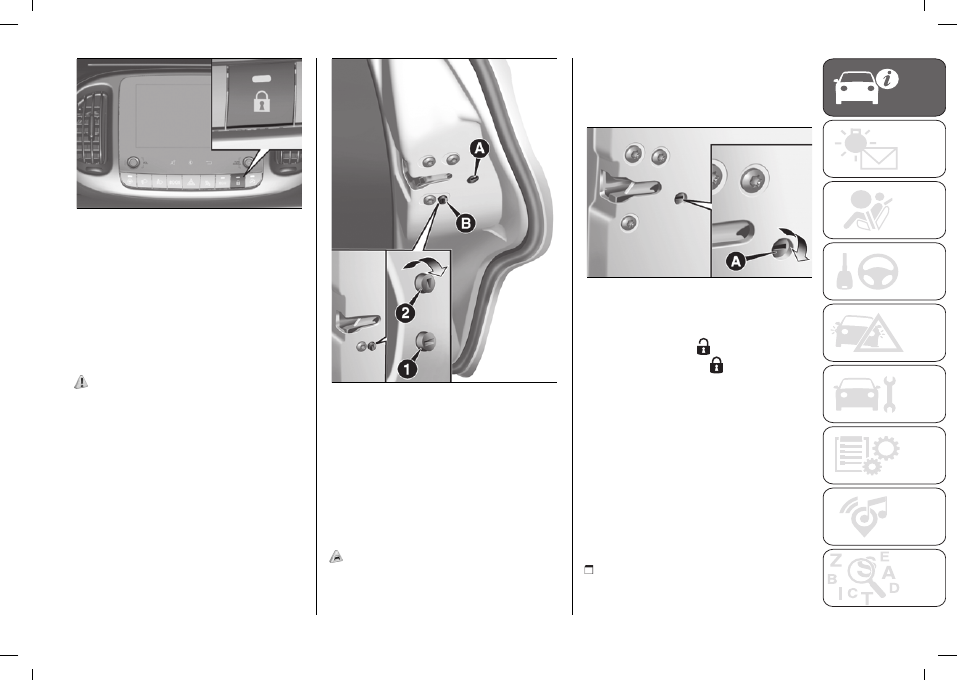
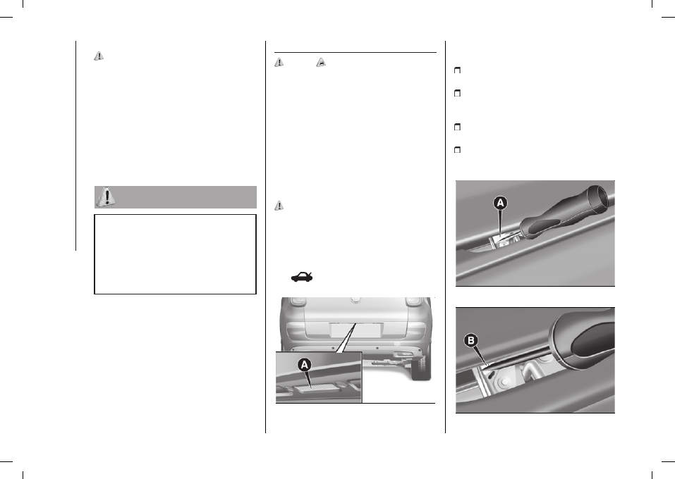
Emergency opening from the inside
Proceed as follows:
remove the rear head restraints and
fully fold the seats;
take the screwdriver provided from
the tool box or the Fix&Go Automatic
container, depending on the version;
use the screwdriver to remove the
yellow tab (A) fig. 69;
then insert the screwdriver in socket
(B) fig. 70 in order to activate the boot
release tab.
69
F0Y0172C
70
F0Y0173C
-------------------------------------------------------------------------------------------------------------------------------------------------------------
51
CLOSING
Take hold of the handle on the inside of
the tailgate and lower it, pressing next
to the lock until it clicks.
WARNING Before closing the boot
make sure that you have the keys,
since the boot is automatically locked.
BOOT INITIALISATION
WARNING If the battery is
disconnected or the protection fuse
blows, the boot opening/closing
mechanism must be reinitialised as
follows:
close all the doors and the boot;
press the
button on the remote
control;
press the
button on the remote
control;
EXTENDING THE boot
See the descriptions in “Removing the
parcel shelf” and “Folding back the
seats” paragraphs for how to expand
the boot.
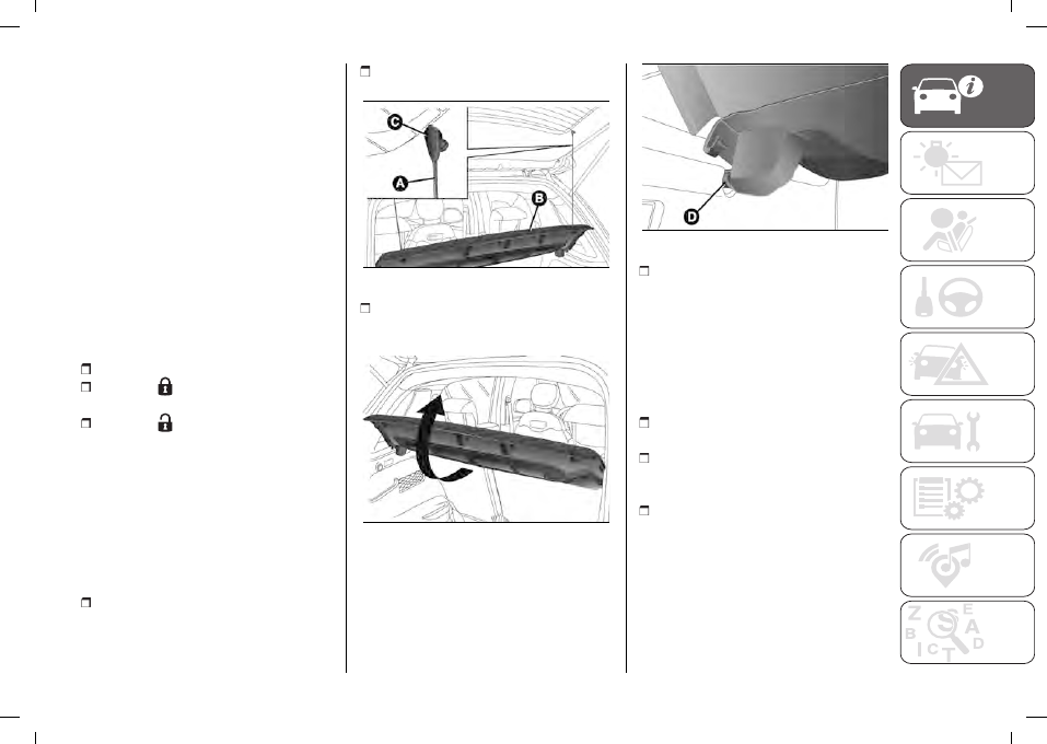
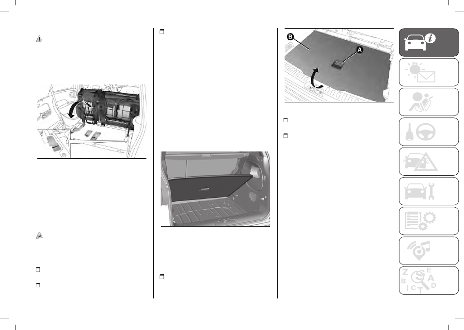
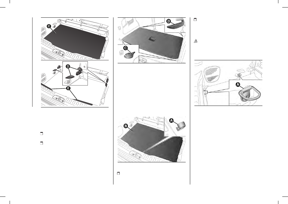
Removing the parcel shelf
Proceed as follows:
release the ends of the two mounting
links (A) fig. 71 of the parcel shelf (B)
by removing the eyelets (C) from the
mounting pins;
raise the rear part of the parcel rack,
operating as illustrated in fig. 72;
71
F0Y0065
free the pins (D) fig. 73 on the outside
of the shelf, then remove the parcel
shelf (B) by pulling it upwards;
72
F0Y0067
73
F0Y0068
after removal, the parcel shelf can
be loaded sideways into the boot
or placed between the front seat
backrests and the folded-back rear
seat cushions (with the boot completely
extended).
Backrest folding (partial extension)
Proceed as follows:
completely lower the rear seat head
restraints;
move the seat belts to the side,
making sure that they are correctly
extended and not twisted;
using lever (A) fig. 74, adjust the seat
into the desired position;
-------------------------------------------------------------------------------------------------------------------------------------------------------------
52
74
F0Y0074
raise lever (B) fig. 75 to fold the
backrest (see fig. 76).
75
F0Y0259
76
F0Y0075
Note
It is advisable to carry out this
procedure from the outside, with the
left hand.
Repositioning the backrest
To bring the backrest back to normal
usage position, lift lever (B) fig. 75 then
raise the backrest.
Backrest and seat folding (total
extension)
Proceed as follows:
completely lower the rear seat head
restraints;
move the seat belts to the side,
making sure that they are correctly
extended and not twisted;
using lever (A) fig. 74 adjust the
seat to "completely forward" position
to achieve maximum boot extension
(depending on the desired position of
the fronts seats);
lift the release lever (B) fig. 77 fold
the left or right section of the backrest:
the backrest and cushion will be folded
forwards automatically (see fig. 78). If
necessary, accompany the backrest
during the initial stage of tilting.
77
F0Y0073
78
F0Y0076
NOTE It is advisable to carry out this
procedure from the outside, with the
left hand.
-------------------------------------------------------------------------------------------------------------------------------------------------------------
53
To reposition the rear seat, push the
backrest backwards as shown in
fig. 79 and secure it (when it clicks
into place, this indicates correct
positioning).
79
F0Y0077
Repositioning the backrest
To bring the backrest back to normal
usage position, lift lever (B) fig. 75
then raise the backrest until vertical
engagement position is reached.
"CARGO MAGIC SPACE"
(for versions/markets, where provided)
12)
The "Cargo Magic Space" adjustable
load platform can be adjusted to three
different heights:
Position 0 (platform completely
lowered)
Position 1 (platform at threshold
level)
Position 2 (platform completely
raised)
Load platform tilting
The load platform can be located in
oblique position (tilted towards the rear
seat backrests, see fig. 80), in order to
facilitate access to the area underneath
the boot (e.g. to pick up the space-
saver wheel or the "Fix&Go Automatic"
kit).
In addition, in this position, the platform
allows any object in the boot to be
correctly blocked, preventing them
from sliding in the case of sharp
braking.
80
F0Y0609C
Access to double load
compartment
To access the double load
compartment, proceed as follows:
grip handle (A) fig. 81 and lift platform
B, holding it with one hand;
81
F0Y0079
place the desired objects in
compartment (C) fig. 82;
then reposition platform (B) correctly
in the housings (D) fig. 82 on the side
panels and rear crossmember E.
WARNING Movements of the load
platform must take place in a central
position relative to the boot.
Repositioning the rear seat
24)
-------------------------------------------------------------------------------------------------------------------------------------------------------------
54
82
F0Y0419
Moving the load platform
To move the load platform from lower
to upper position, proceed as follows:
grip handle (A) fig. 81 and lift the
platform (B) holding it with one hand;
correctly position the platform (B) on
the respective housings (C) e (D) fig. 83
provided on the side panels.
83
F0Y0082
“Fix&Go Automatic” kit access (or
removing the space-saver wheel)
To access the "Fix&Go Automatic"
quick tyre inflation kit (for use, see
contents of the "In an emergency"
chapter) or to remove the space-saver
wheel (for versions/markets, where
provided) and its toolbox, proceed as
follows:
84
F0Y0083
grip the handle (A) fig. 81and remove
the platform (B);
pull the tab (A) fig. 84 and lift the mat
(B).
ANCHORING YOUR LOAD
(for versions/markets, where provided)
26)
There are two hooks (A) fig. 85 inside
the boot for attaching cables which can
secure the load carried.
85
F0Y0063
A further two hooks are located on the
rear crossmember.
Two hooks are also available on the
side panels to fix loads which are not
excessively heavy (e.g. bags).
To use the hooks, press button (A)
fig. 86.
WARNING Do not apply, on a single
hook, a load greater than 10 kg.
-------------------------------------------------------------------------------------------------------------------------------------------------------------
55
86
F0Y0062
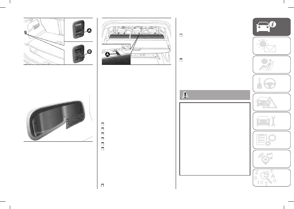
STORAGE
COMPARTMENTS
There are two storage compartments
fig. 87 on the side panels.
87
F0Y0078
OBJECT-COVERING
CURTAINS
Two object-covering curtains are
present on the front part of the
luggage-covering curtain.
88
F0Y0376
To use the curtains pull tabs (A) fig. 88
and engage them with the rear seat
head restraint supports, as shown in
the figure.
LOADING ADVICE
(500L PRO versions)
The car has been designed and
certified according to certain maximum
weights:
kerb weight
payload
total weight
maximum weight on front axle
maximum weight on rear axle
Towable weight.
Each of these must be strictly observed
and must never be exceeded in any
case.
Other simple suggestions can improve
driving safety and comfort, and car
duration:
distribute the load evenly over
the platform. If it is necessary to
concentrate it in a single area, choose
an area mid-way between both axles;
remember that the lower the load,
the lower the centre of gravity of the
vehicle, making for a safer drive:
therefore always position the heaviest
goods lower down;
remember that the dynamic
behaviour of the car is affected by
the weight transported: in particular,
the stopping distances are longer,
especially at high speeds.
24)
Make sure the backrest is properly
secured at both sides to prevent it moving
forward in the event of sharp braking, with
possible impact with the occupants.
25)
Do not move the seat if a child is
seated on the same or sitting in the
suitable child restraint system.
26)
Abrupt braking or occasional impacts
may cause sudden movements of the load
with consequent situations of hazard for
the driver and passengers: before setting
off, secure the load tightly using the hooks
provided. For securing use cables, ropes
or belts strong enough to hold the items to
be secured.
27)
Be careful not to hit objects on the roof
rack when you open the tailgate.
-------------------------------------------------------------------------------------------------------------------------------------------------------------
56
11)
Before tilting the seat backrest fully,
remove any objects laid on it.
12)
The dimensions of the platform permit
a maximum capacity of distributed weight
of 70 kg (in position 1) or 40 kg (in position
2): do not load objects with a higher
weight.
ROOF RACK/SKI
RACK
28) 29) 30)
13)
The attachments are located in the
areas illustrated in fig. 89 and can only
be accessed with the doors open.
Lineaccessori Fiat has a dedicated roof
rack/ski rack for this car.
89
F0Y0131
28)
After travelling for a few kilometres,
check to ensure that the fixing screws for
the attachments are well tightened.
29)
Never exceed the maximum
permitted loads (see chapter "Technical
specifications").
30)
Evenly distribute the load and take
into account, when driving, the increased
responsiveness of the vehicle to side wind.
13)
Fully comply with the regulations in
force concerning maximum clearance.
DUALDRIVE
ELECTRIC POWER
STEERING
(for versions/markets, where provided)
This only operates with the ignition key
turned to MAR and engine running.
Electric power steering allows the force
required at the steering wheel to be
adapted to the driving conditions.
POWER STEERING
ON/OFF
31) 32)
To engage/disengage the electric
power steering press button fig. 90.
The LED above the button switches on
to indicate that the system is active.
90
F0Y0646C
When the power steering is on, the
steering wheel effort is lighter, making
parking easier: therefore, this function
is particularly useful for driving in city
centres.
31)
It is absolutely forbidden to carry
out any after-market operation involving
steering system or steering column
modifications (e.g. installation of anti-theft
device) that could adversely affect
performance and safety, invalidate
the warranty and also result in non-
compliance of the car with type-approval
requirements.
32)
Before performing any maintenance
operations, always turn off the engine and
remove the key from the ignition to lock
the steering column (especially when the
car wheels are not touching the ground). If
-------------------------------------------------------------------------------------------------------------------------------------------------------------
57
this is not possible (for example if the key
needs to be turned to MAR or the engine
must be running), remove the main fuse
that protects the electric power steering.
PROTECTING THE
ENVIRONMENT
33)
Petrol versions
The following devices are used for
reducing petrol fuel engine emissions:
catalytic converter, oxygen sensors and
evaporation control system.
Do not let the engine run, even for a
test, with one or more spark plugs
disconnected.
Diesel versions
The following devices are used for
reducing diesel fuel engine emissions:
oxidising catalytic converter, exhaust
gas recirculation system (EGR) and
particulate filter (DPF).
DIESEL PARTICULATE
FILTER (DPF)
(for versions/markets, where provided)
The Diesel Particulate Filter is a
mechanical filter, integral to the exhaust
system, that physically traps carbon
particles present in the exhaust gases
of diesel engines.
Since this filter physically traps
particulate, it should be periodically
regenerated (cleaned) at regular
intervals by burning carbon particles.
The regeneration procedure is
controlled automatically by the engine
control unit according to the filter
conditions and car use conditions.
During the regeneration there may be
a limited increase in the engine idle
speed, fan activation, a limited increase
in fumes and high temperatures at the
exhaust.
These are not faults; they do not impair
normal car performance or damage the
environment.
If the dedicated message is displayed,
see contents of "Warning lights and
messages" chapter.
33)
The catalytic converter and particulate
filter (DPF) reach very high temperatures
during normal operation. Therefore, do
not park the car on flammable materials
(e.g. grass, dry leaves, pine needles etc.)
to avoid the risk of fire.
RED SPECIAL
SERIES
(where provided)
Some components of the
car underwent antimicrobial
treatments, as detailed below. No
specific precautions are required
for the normal use of the car and
components treated with biocide
substances.
The reconfigurable load platform was
treated with a biocide substance
having antiviral properties based on the
the active ingredient Silver Chloride.
The seat fabric was treated with a
biocide substance with antiviral and
antibacterial properties based on the
active ingredient Alkyl (C12-C16)
Dimethylbenzyl Ammonium Chloride.
The steering wheel upholstery was
treated a with biocide substances with
antibacterial and antifungal properties
based on the active ingredients Zinc
Pyrithione and Thiabendazole.
The air cleaner of the climate control
system was treated with a biocide
substance having antibacterial and
antiviral properties based on the active
ingredient Dimethyltetradecyl[3-
(trimethoxysilyl)propyl]ammonium
chloride.
-------------------------------------------------------------------------------------------------------------------------------------------------------------
KNOWING THE INSTRUMENT PANEL
58
KNOWING THE INSTRUMENT PANEL
This section of the handbook provides
all information that is useful for getting
to know, interpreting, and using the
instrument panel correctly.
DASHBOARD AND INSTRUMENT
PANEL. . . . . . . . . . 59
DISPLAY. . . . . . . . . . 61
TRIP COMPUTER . . . . . . 63
EOBD SYSTEM . . . . . . ... 64
WARNING LIGHTS AND
MESSAGES . . . . . . . . 65
-------------------------------------------------------------------------------------------------------------------------------------------------------------
59
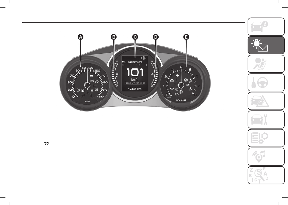
DASHBOARD AND INSTRUMENT PANEL
The instrument background colour and type may vary according to the versions.
91
F0Y0639C
A. Speedometer / B. Digital fuel level gauge / C. Display / D. Digital engine coolant thermometer / E. Tachometer
The warning lights on the instrument panel may change according to the version/trim level (e.g. Dualogic gearbox, etc.) of the
vehicle. The
warning light is present on Diesel versions only. On Diesel versions, the maximum engine speed (red range on
the rev counter) corresponds to 7000 rpm.
-------------------------------------------------------------------------------------------------------------------------------------------------------------
Нет комментариевНе стесняйтесь поделиться с нами вашим ценным мнением.
Текст