
Nissan Pathfinder (2005 year). Manual — part 92
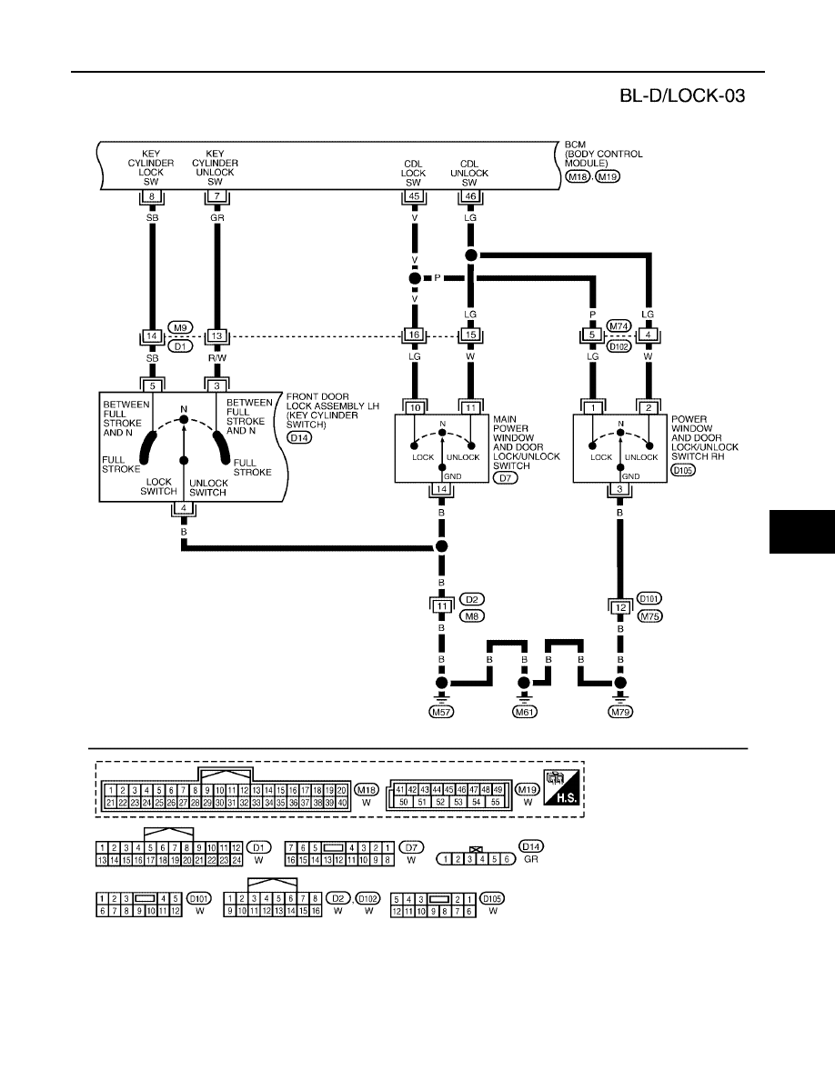
POWER DOOR LOCK SYSTEM
BL-23
C
D
E
F
G
H
J
K
L
M
A
B
BL
2005 Pathfinder
WIWA0540E
BL-24
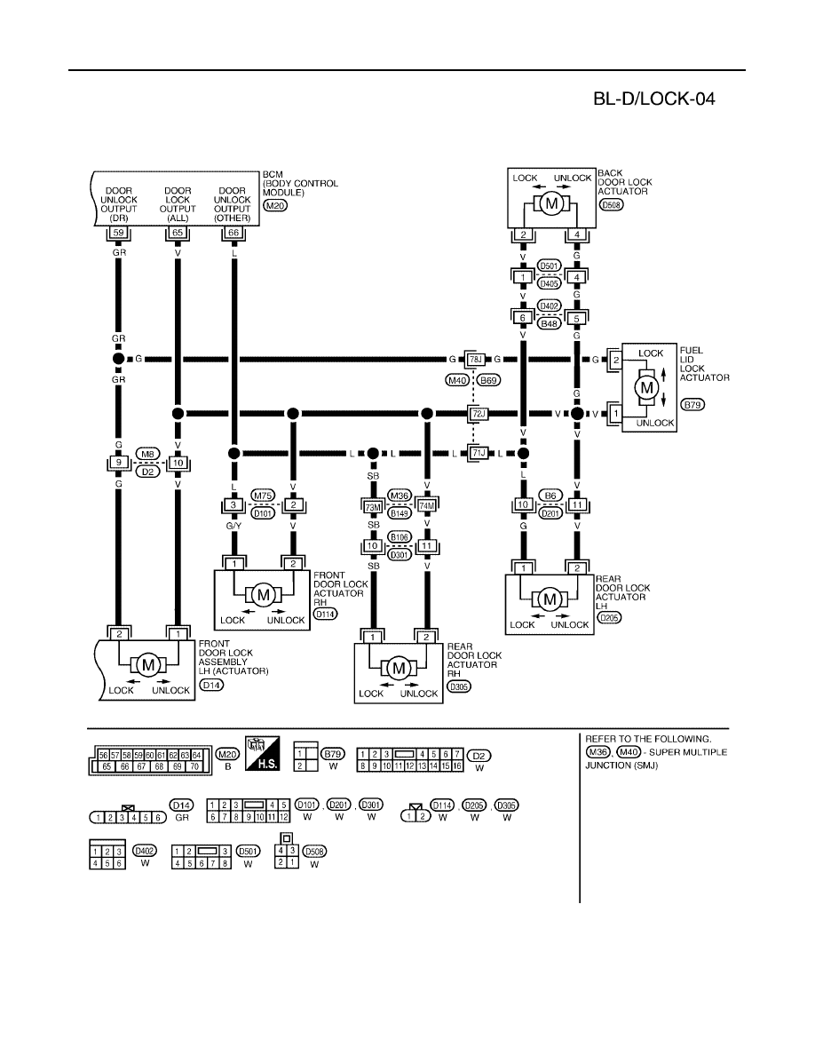
POWER DOOR LOCK SYSTEM
2005 Pathfinder
WIWA0541E

POWER DOOR LOCK SYSTEM
BL-25
C
D
E
F
G
H
J
K
L
M
A
B
BL
2005 Pathfinder
Terminals and Reference Value for BCM
EIS003Y4
Work Flow
EIS003Y5
1.
Check the symptom and customer's requests.
2.
Understand the outline of system. Refer to
.
3.
According to the trouble diagnosis chart, repair or replace the cause of the malfunction. Refer to
"Trouble Diagnoses Symptom Chart"
.
4.
Does power door lock system operate normally? OK: GO TO 5, NG: GO TO 3.
5.
Inspection End.
Termi-
nal
Wire
Color
Item
Condition
Voltage (V)
(Approx.)
7
GR
Front door lock assembly LH
(key cylinder switch) (unlock)
OFF (neutral)
→
ON (unlocked)
5
→
0
8
SB
Front door lock assembly LH
(key cylinder switch) (lock)
OFF (neutral)
→
ON (locked)
5
→
0
12
LG
Front door switch RH
Door close (OFF)
→
Door open (ON)
Battery voltage
→
0
13
L
Rear door switch RH
Door close (OFF)
→
Door open (ON)
Battery voltage
→
0
37
B
Key switch (insert)
Key inserted in IGN key cylinder (ON)
→
Key removed from IGN key cylinder
(OFF)
Battery voltage
→
0
39
L
CAN-H
—
—
40
P
CAN-L
—
—
43
Y
Back door switch
Door open (ON)
→
Door close (OFF)
0
→
Battery voltage
45
V
Lock switch signal
Door lock and unlock switch (neutral)
→
Door lock and unlock switch (locked)
Battery voltage
→
0
46
LG
Unlock switch signal
Door lock and unlock switch (neutral)
→
Door lock and unlock switch (unlocked)
Battery voltage
→
0
47
GR
Front door switch LH
Door close (OFF)
→
Door open (ON)
Battery voltage
→
0
48
P
Rear door switch LH
Door close (OFF)
→
Door open (ON)
Battery voltage
→
0
57
R/Y
Power source (BAT)
—
Battery voltage
59
GR
Front door lock assembly LH
and fuel lid door lock actuator
(unlock)
Door lock and unlock switch
(neutral
→
unlocked)
0
→
Battery voltage
65
V
All door lock actuators (lock)
Door lock and unlock switch
(neutral
→
lock)
0
→
Battery voltage
66
L
Front door lock actuator RH,
rear door lock actuators LH/RH
and back door lock actuator
(unlock)
Door lock and unlock switch
(neutral
→
unlocked)
0
→
Battery voltage
67
B
Ground
—
0
70
W
Power source (BAT)
—
Battery voltage
BL-26
POWER DOOR LOCK SYSTEM
2005 Pathfinder
CONSULT–II Function (BCM)
EIS003Y6
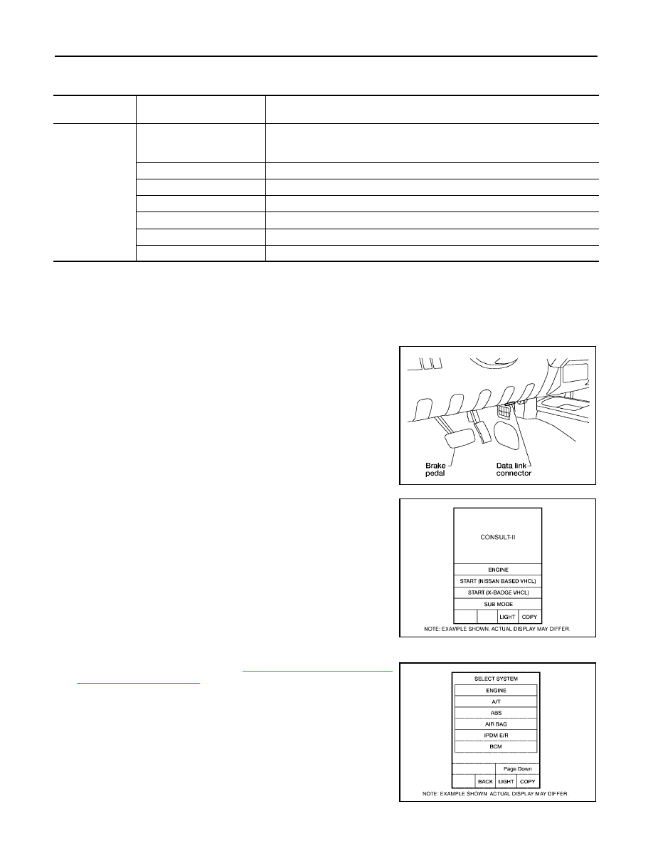
CONSULT-II can display each diagnostic item using the diagnostic test modes shown following.
CONSULT–II INSPECTION PROCEDURE
"DOOR LOCK"
CAUTION:
If CONSULT-II is used with no connection of CONSULT-II CONVERTER, malfunctions might be
detected in self-diagnosis depending on control unit which carries out CAN communication.
1.
Turn ignition switch OFF.
2.
Connect CONSULT-II and CONSULT-II CONVERTER to the
data link connector.
3.
Turn ignition switch ON.
4.
Touch “START (NISSAN BASED VHCL)”.
5.
Touch “BCM”.
If "BCM" is not indicated, refer to
.
BCM diagnostic
test item
Diagnostic mode
Description
Inspection by part
WORK SUPPORT
Supports inspections and adjustments. Commands are transmitted to the BCM
for setting the status suitable for required operation, input/output signals are
received from the BCM and received data is displayed.
DATA MONITOR
Displays BCM input/output data in real time.
ACTIVE TEST
Operation of electrical loads can be checked by sending drive signal to them.
SELF-DIAG RESULTS
Displays BCM self-diagnosis results.
CAN DIAG SUPPORT MNTR
The result of transmit/receive diagnosis of CAN communication can be read.
ECU PART NUMBER
BCM part number can be read.
CONFIGURATION
Performs BCM configuration read/write functions.
BBIA0538E
BCIA0029E
BCIA0030E
POWER DOOR LOCK SYSTEM
BL-27
C
D
E
F
G
H
J
K
L
M
A
B
BL
2005 Pathfinder
6.
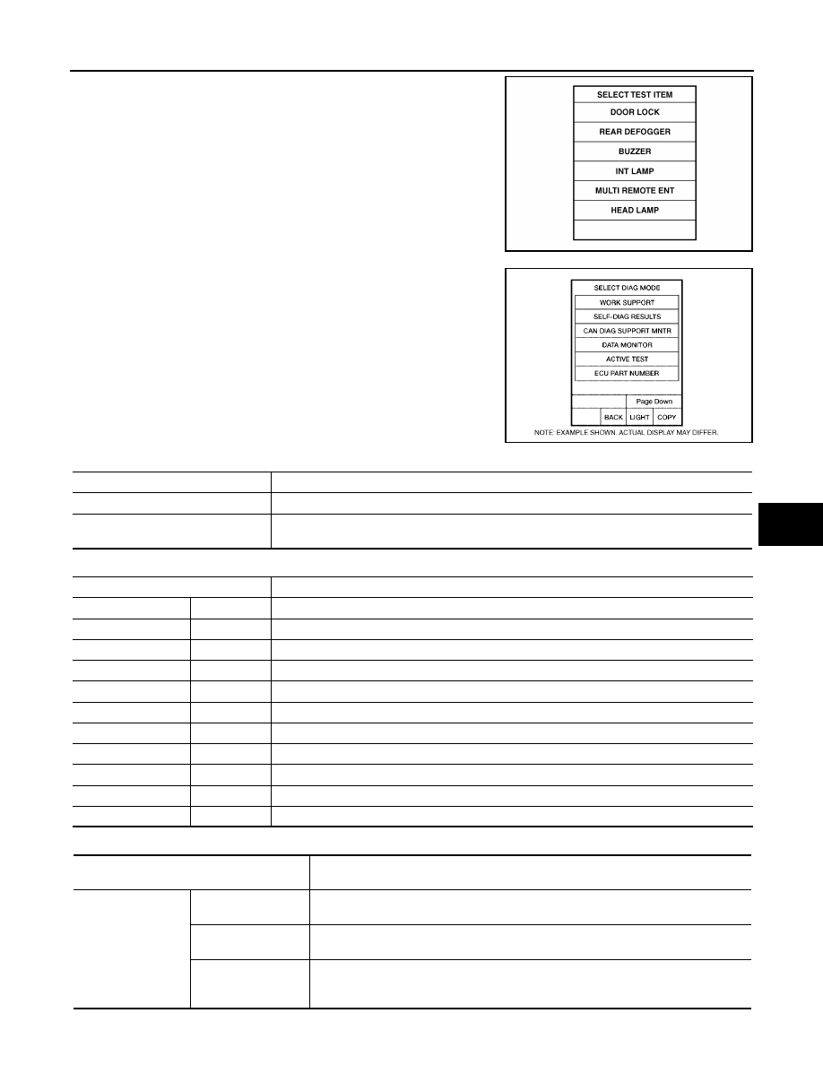
Touch “DOOR LOCK”.
7.
Select diagnosis mode.
"WORK SUPPORT", “DATA MONITOR” and “ACTIVE TEST”
are available.
WORK SUPPORT
DATA MONITOR
ACTIVE TEST
LIIA1137E
BCIA0031E
Work item
Content
DOOR LOCK-UNLOCK SET
Select unlock mode can be changed in this mode. Selects ON-OFF of select unlock mode.
ANTI-LOCK OUT SET
Key reminder door mode can be changed in this mode. Selects ON-OFF of key reminder door
mode.
Monitor item "OPERATION"
Content
KEY ON SW
"ON/OFF"
Indicates [ON/OFF] condition of key switch.
CDL LOCK SW
"ON/OFF"
Indicates [ON/OFF] condition of lock signal from lock/unlock switch LH and RH.
CDL UNLOCK SW
"ON/OFF"
Indicates [ON/OFF] condition of unlock signal from lock/unlock switch LH and RH.
KEY CYL LK-SW
"ON/OFF"
Indicates [ON/OFF] condition of lock signal from key cylinder.
KEY CYL UN-SW
"ON/OFF"
Indicates [ON/OFF] condition of unlock signal from key cylinder.
IGN ON SW
"ON/OFF"
Indicates [ON/OFF] condition of ignition switch.
DOOR SW–DR
"ON/OFF"
Indicates [ON/OFF] condition of front door switch LH.
DOOR SW–AS
"ON/OFF"
Indicates [ON/OFF] condition of front door switch RH.
DOOR SW–RR
"ON/OFF"
Indicates [ON/OFF] condition of rear door switch RH.
DOOR SW–RL
"ON/OFF"
Indicates [ON/OFF] condition of rear door switch LH.
BACK DOOR SW
"ON/OFF"
Indicates [ON/OFF] condition of back door switch.
Test item
Content
DOOR LOCK
ALL LOCK/UNLOCK
This test is able to check all door lock actuators lock operation. These actuators lock
when "ON" on CONSULT–II screen is touched.
DR UNLOCK
This test is able to check front door lock assembly LH unlock operation.These actua-
tors lock when "ON" on CONSULT–II screen is touched.
OTHER UNLOCK
This test is able to check door lock actuators (except front door lock assembly LH)
unlock operation.These actuators unlock when "ON" on CONSULT–II screen is
touched.
BL-28
POWER DOOR LOCK SYSTEM
2005 Pathfinder
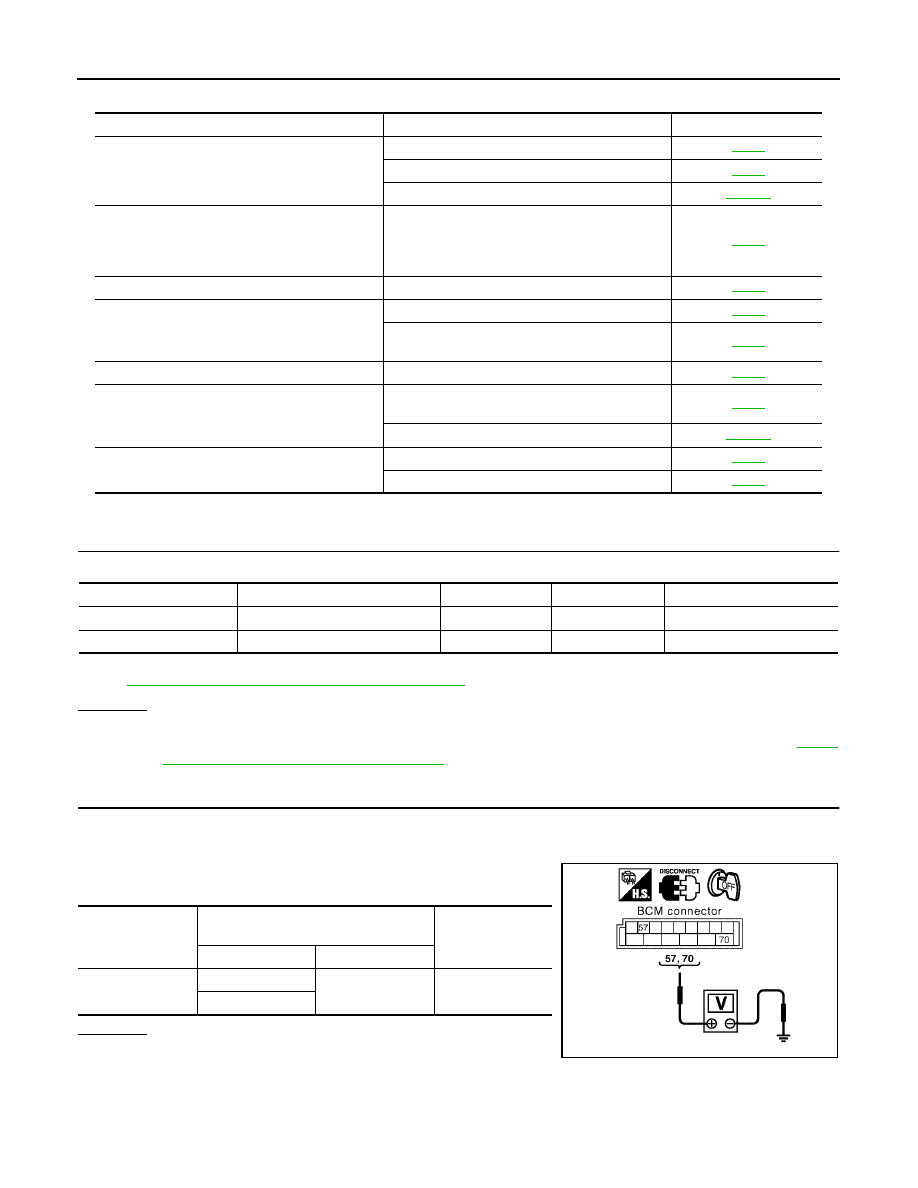
Trouble Diagnoses Symptom Chart
EIS003Y7
BCM Power Supply and Ground Circuit Check
EIS003Y8
1.
CHECK FUSE
Check the following BCM fuse and fusible link.
NOTE:
Refer to
BL-16, "Component Parts and Harness Connector Location"
.
OK or NG
OK
>> GO TO 2.
NG
>> If fuse is blown, be sure to eliminate cause of problem before installing new fuse, refer to
"POWER SUPPLY ROUTING CIRCUIT"
.
2.
CHECK POWER SUPPLY CIRCUIT
1.
Turn ignition switch OFF.
2.
Disconnect BCM.
3.
Check voltage between BCM connector M20 terminals 57, 70
and ground.
OK or NG
OK
>> GO TO 3.
NG
>> Repair or replace harness.
Symptom
Repair order
Refer to page
Key reminder door system does not operate
properly.
1. Door switch check
2. Key switch (Insert) check
3. Replace BCM.
Power door lock does not operate with door lock
and unlock switch on main power window and
door lock/unlock switch or power window and
door lock/unlock switch RH.
1. Door lock/unlock switch check
Front door lock assembly LH does not operate.
1. Front door lock assembly LH (actuator) check
Specific door lock actuator does not operate.
1. Front door lock assembly RH (actuator) check
2. Back door lock actuator and rear door lock
actuator LH/RH check
Fuel lid door lock actuator does not operate.
1. Fuel lid door lock actuator check
Power door lock does not operate with front door
key cylinder LH operation.
1. Front door lock assembly LH (key cylinder
switch) check
2. Replace BCM.
Power door lock does not operate.
1. BCM power supply and ground circuit check
2. Door lock/unlock switch check
Component Parts
Terminal No. (SIGNAL)
Ampere
No.
Location
BCM
57 (BAT power supply)
10A
18
Fuse block (J/B)
BCM
70 (BAT power supply)
50A
g
Fuse and fusible link box
Connector
Terminals
(Wire color)
Voltage (V)
(Approx.)
(+)
(-)
M20
57
Ground
Battery voltage
70
LIIA1039E
POWER DOOR LOCK SYSTEM
BL-29
C
D
E
F
G
H
J
K
L
M
A
B
BL
2005 Pathfinder
3.
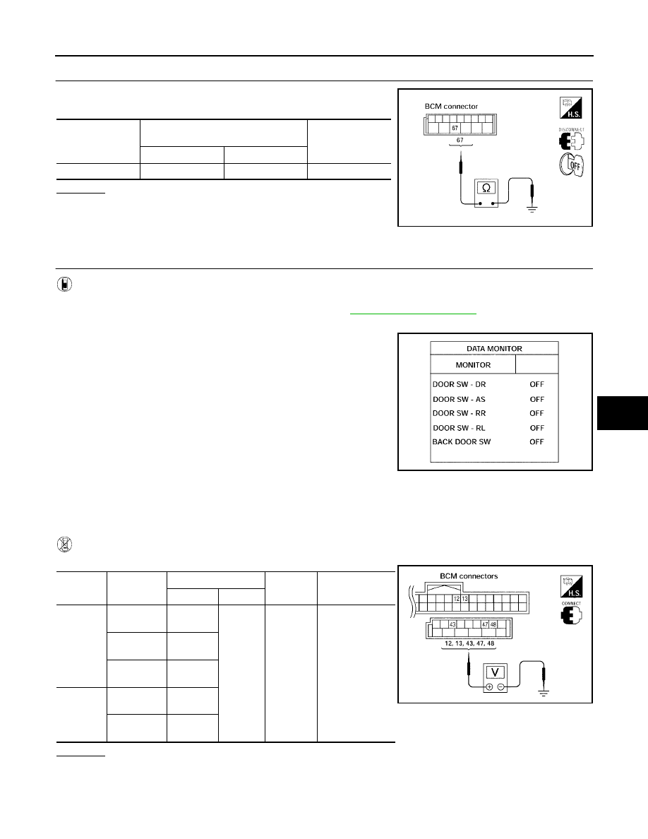
CHECK GROUND CIRCUIT
Check continuity between BCM connector M20 terminal 67 and
ground.
OK or NG
OK
>> Power supply and ground circuit is OK.
NG
>> Repair or replace harness.
Door Switch Check
EIS003Y9
1.
CHECK DOOR SWITCHES INPUT SIGNAL
With CONSULT-II
Check door switches ("DOOR SW-DR", "DOOR SW-AS", "DOOR SW-RL", "DOOR SW-RR", "BACK DOOR
SW") in DATA MONITOR mode with CONSULT–II. Refer to
.
●
When any doors are open:
●
When any doors are closed:
Without CONSULT-II
Check voltage between BCM connector M18 or M19 terminals 12, 13, 42, 43, 47, 48 and ground.
OK or NG
OK
>> System is OK.
NG
>> GO TO 2.
Connector
Terminals
(Wire color)
Continuity
(+)
(-)
M20
67
Ground
Yes
LIIA1040E
DOOR SW-DR
: ON
DOOR SW-AS
: ON
DOOR SW-RL
: ON
DOOR SW-RR
: ON
BACK DOOR SW
: ON
DOOR SW-DR
: OFF
DOOR SW-AS
: OFF
DOOR SW-RL
: OFF
DOOR SW-RR
: OFF
BACK DOOR SW
: OFF
LIIA0665E
Connec-
tor
Item
Terminals (Wire color)
Condition
Voltage (V)
(Approx.)
(+)
(–)
M19
Back door
switch
43
Ground
Open
↓
Closed
0
↓
Battery voltage
Front door
switch LH
47
Rear door
switch LH
48
M18
Front door
switch RH
12
Rear door
switch RH
13
LIIA1041E
BL-30
POWER DOOR LOCK SYSTEM
2005 Pathfinder
2.
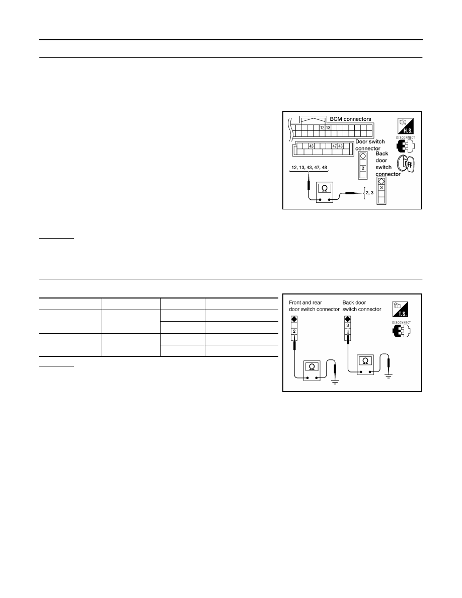
CHECK DOOR SWITCH CIRCUIT
1.
Turn ignition switch OFF.
2.
Disconnect door switch and BCM.
3.
Check continuity between door switch connector B8 (Front LH), B108 (Front RH), B18 (Rear LH), B116
(Rear RH) terminal 2 or D502 (Back) terminal 3 and BCM connector M18, M19 terminals 12, 13, 42, 43,
47 and 48.
4.
Check continuity between door switch connector B8 (Front LH),
B108 (Front RH), B18 (Rear LH), B116 (Rear RH) terminal 2 or
D502 (Back) terminal 3 and ground.
OK or NG
OK
>> GO TO 3.
NG
>> Repair or replace harness.
3.
CHECK DOOR SWITCHES
Check continuity between door switch connector terminals.
OK or NG
OK
>> Check switch case ground condition (front and rear
door) or ground circuit (back door).
NG
>> Replace door switch.
2 - 47
: Continuity should exist.
2 - 12
: Continuity should exist.
2 - 48
: Continuity should exist.
2 - 13
: Continuity should exist.
3 - 43
: Continuity should exist.
2 - Ground
: Continuity should not exist.
3 - Ground
: Continuity should not exist.
LIIA1139E
Terminal
Condition
Continuity
Door switch (front
and rear)
2 – Ground
Open
Yes
Closed
No
Door switch (back)
3 – Ground
Open
Yes
Closed
No
LIIA1146E
Нет комментариевНе стесняйтесь поделиться с нами вашим ценным мнением.
Текст