
Nissan Pathfinder (2005 year). Manual — part 406
AUTOMATIC DRIVE POSITIONER
SE-43
C
D
E
F
G
H
J
K
L
M
A
B
SE
2005 Pathfinder
4.
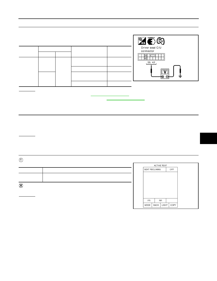
CHECK DRIVER SEAT CONTROL UNIT OUTPUT SIGNAL
1.
Connect the driver seat control unit and sliding motor LH.
2.
Check voltage between driver seat control unit connector and
ground.
OK or NG
OK
>> Replace sliding motor. Refer to
.
NG
>> Replace driver seat control unit. Refer to
.
Reclining Motor LH Circuit Inspection
EIS0045G
1.
CHECK SEAT RECLINING MECHANISM
Check the following.
●
Operation malfunction caused by an interference with the center pillar or center console
●
Operation malfunction and interference with other parts by poor installation
OK or NG
OK
>> GO TO 2.
NG
>> Repair or replace the malfunctioning part and check again.
2.
CHECK FUNCTION
With CONSULT-II
Check operation with “SEAT RECLINING” in ACTIVE TEST.
Without CONSULT-II
GO TO 3.
OK or NG
OK
>> Reclining motor LH circuit is OK.
NG
>> GO TO 3.
Connector
Terminals
Condition
Voltage (V)
(Approx.)
(+)
(–)
P3
35
Ground
Sliding switch ON
(FORWARD operation)
Battery voltage
Other than above
0
42
Sliding switch ON
(BACKWARD operation)
Battery voltage
Other than above
0
PIIA4801E
Test item
Description
SEAT
RECLINING
The reclining motor LH is activated by receiving the drive signal.
PIIA0268E
SE-44
AUTOMATIC DRIVE POSITIONER
2005 Pathfinder
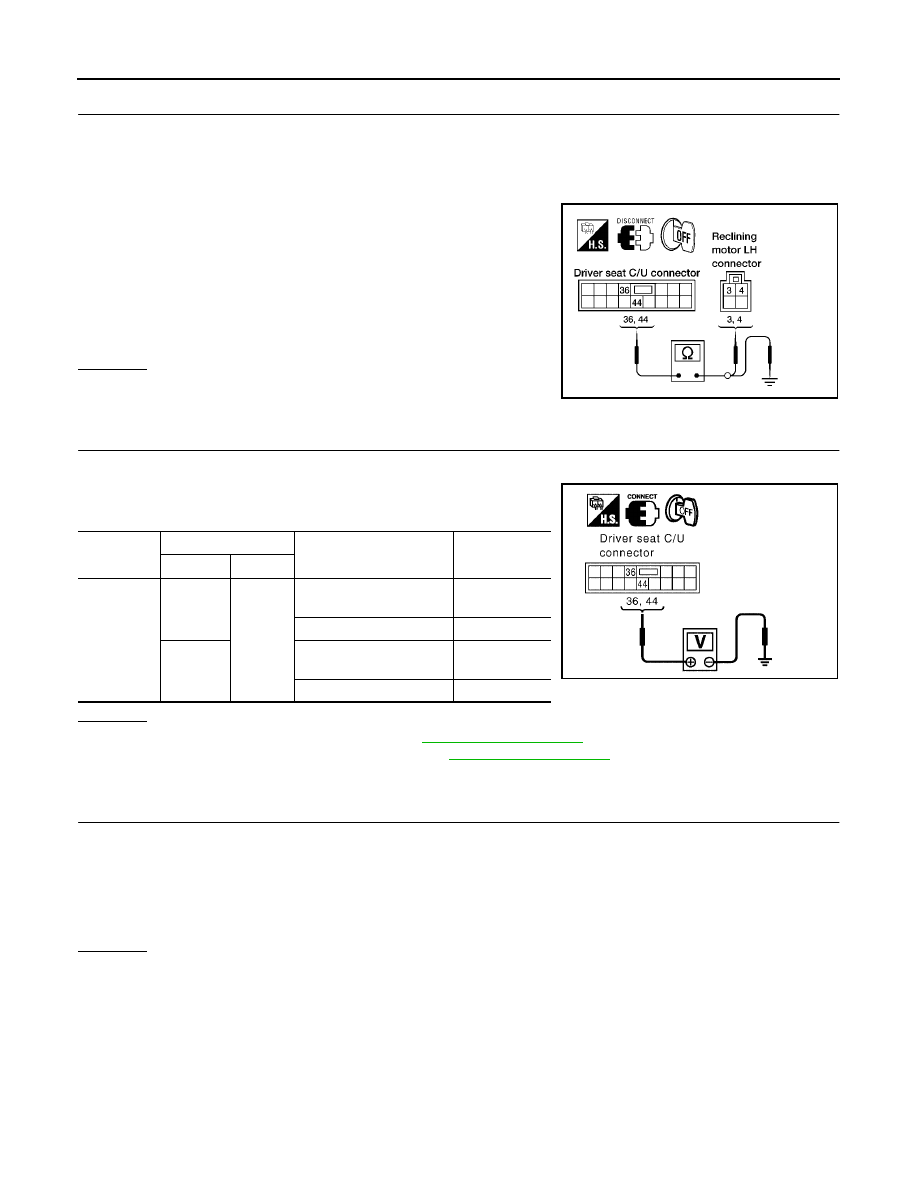
3.
CHECK RECLINING MOTOR CIRCUIT HARNESS CONTINUITY
1.
Turn ignition switch OFF.
2.
Disconnect driver seat control unit and reclining motor LH.
3.
Check continuity between driver seat control unit connector P3 terminals 36, 44 and reclining motor LH
connector P5 terminals 3, 4.
4.
Check continuity between driver seat control unit connector P3
terminals 36, 44 and ground.
OK or NG
OK
>> GO TO 4.
NG
>> Repair or replace harness.
4.
CHECK DRIVER SEAT CONTROL UNIT OUTPUT SIGNAL
1.
Connect the driver seat control unit and reclining motor LH.
2.
Check voltage between driver seat control unit connector and
ground.
OK or NG
OK
>> Replace reclining motor LH. Refer to
.
NG
>> Replace driver seat control unit. Refer to
.
Lifting Motor (Front) Circuit Inspection
EIS0045H
1.
CHECK FRONT END SEAT LIFTING MECHANISM
Check the following.
●
Operation malfunction caused by lifter mechanism deformation, pinched harness or other foreign materi-
als
●
Operation malfunction caused by foreign materials adhered to the lifting motor (front) or lead screws
●
Operation malfunction and interference with other parts by installation
OK or NG
OK
>> GO TO 2.
NG
>> Repair or replace the malfunctioning part and check again.
36 - 4
: Continuity should exist.
44 - 3
: Continuity should exist.
36 - Ground
: Continuity should not exist.
44 - Ground
: Continuity should not exist.
LIIA0697E
Connector
Terminals
Condition
Voltage (V)
(Approx.)
(+)
(–)
P3
36
Ground
Reclining switch ON
(FORWARD operation)
Battery voltage
Other than above
0
44
Reclining switch ON
(BACKWARD operation)
Battery voltage
Other than above
0
PIIA4802E
AUTOMATIC DRIVE POSITIONER
SE-45
C
D
E
F
G
H
J
K
L
M
A
B
SE
2005 Pathfinder
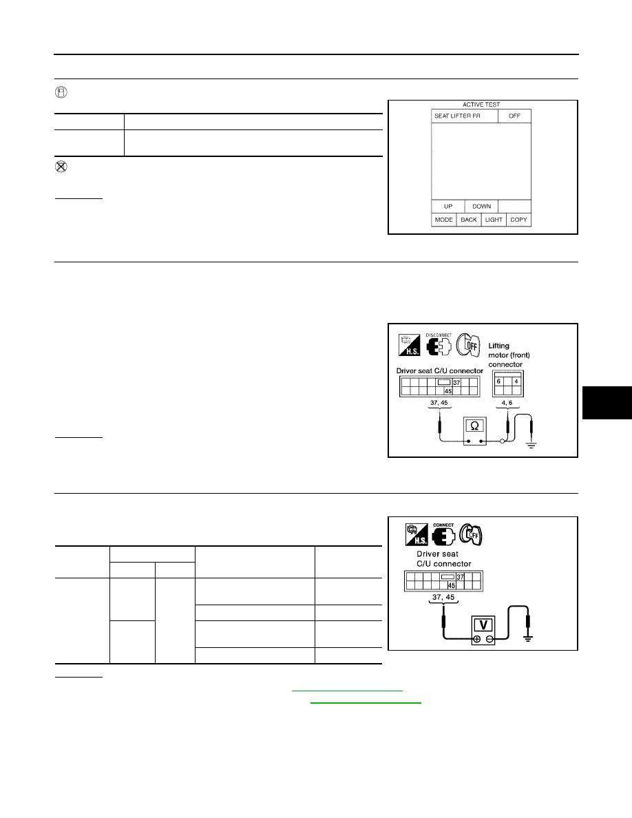
2.
CHECK FUNCTION
With CONSULT-II
Check operation with “SEAT LIFTER FR” in ACTIVE TEST.
Without CONSULT-II
GO TO 3.
OK or NG
OK
>> Lifting motor (front) circuit is OK.
NG
>> GO TO 3.
3.
CHECK LIFTING MOTOR (FRONT) CIRCUIT HARNESS CONTINUITY
1.
Turn ignition switch OFF.
2.
Disconnect driver seat control unit and lifting motor (front).
3.
Check continuity between driver seat control unit connector P3 terminals 37, 45 and lifting motor (front)
connector P6 terminals 4, 6.
4.
Check continuity between driver seat control unit connector P3
terminals 37, 45 and ground.
OK or NG
OK
>> GO TO 4.
NG
>> Repair or replace harness.
4.
CHECK DRIVER SEAT CONTROL UNIT OUTPUT SIGNAL
1.
Connect the driver seat control unit and lifting motor (front).
2.
Check voltage between driver seat control unit connector and
ground.
OK or NG
OK
>> Replace lifting motor (front). Refer to
.
NG
>> Replace driver seat control unit. Refer to
.
Test item
Description
SEAT
LIFTER FR
The lifting motor (front) is activated by receiving the drive signal.
PIIA0271E
37 - 6
: Continuity should exist.
45 - 4
: Continuity should exist.
37 - Ground
: Continuity should not exist.
45 - Ground
: Continuity should not exist.
LIIA0698E
Connector
Terminals
Condition
Voltage (V)
(Approx)
(+)
(–)
P3
37
Ground
Lifting switch (front) ON
(DOWN operation)
Battery voltage
Other than above
0
45
Llifting switch (front) ON
(UP operation)
Battery voltage
Other than above
0
PIIA4805E
SE-46
AUTOMATIC DRIVE POSITIONER
2005 Pathfinder
Lifting Motor (Rear) Circuit Inspection
EIS0045I
1.
CHECK REAR SEAT LIFTING MECHANISM
Check the following.
●
Operation malfunction caused by lifter mechanism deformation or pinched harness or other foreign mate-
rials
●
Operation malfunction caused by foreign materials adhered to the lifting motor (rear) or lead screws
●
Operation malfunction and interference with other parts by poor installation
OK or NG
OK
>> GO TO 2.
NG
>> Repair or replace the malfunctioning part and check again.
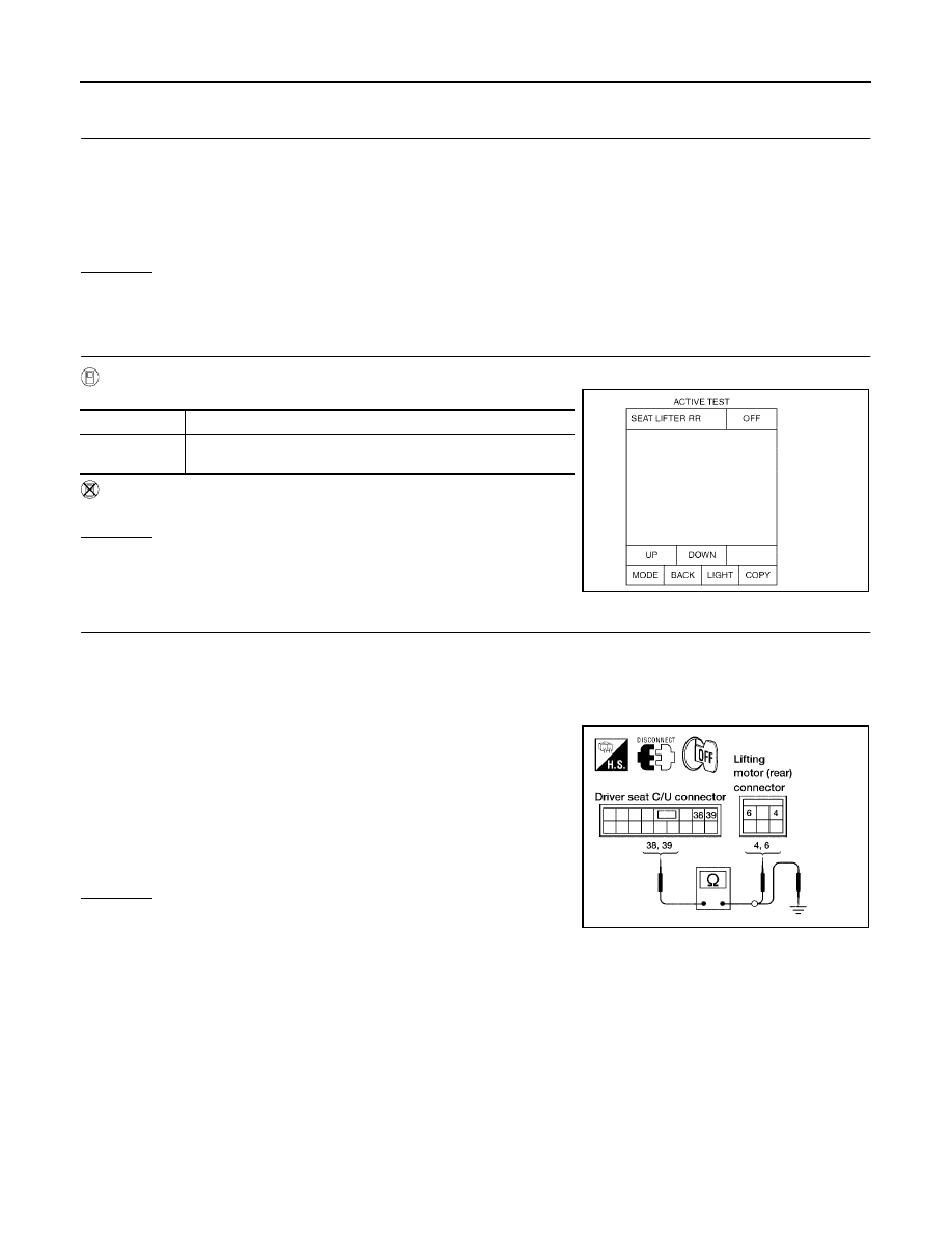
2.
CHECK FUNCTION
With CONSULT-II
Check operation with “SEAT LIFTER RR” in ACTIVE TEST.
Without CONSULT-II
GO TO 3.
OK or NG
OK
>> Lifting motor (rear) circuit is OK.
NG
>> GO TO 3.
3.
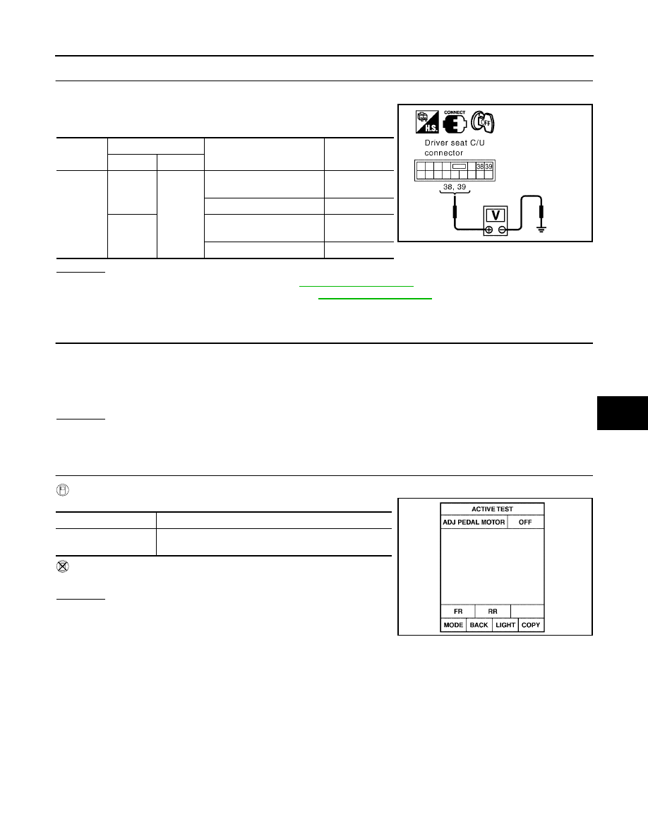
CHECK LIFTING MOTOR (REAR) CIRCUIT HARNESS CONTINUITY
1.
Turn ignition switch OFF.
2.
Disconnect driver seat control unit and lifting motor (rear).
3.
Check continuity between driver seat control unit connector P3 terminals 38, 39 and lifting motor (rear)
connector P7 terminals 4, 6.
4.
Check continuity between driver seat control unit P3 terminals
38, 39 and ground.
OK or NG
OK
>> GO TO 4.
NG
>> Repair or replace harness.
Test item
Description
SEAT LIFTER
RR
The lifting motor (rear) is activated by receiving the drive signal.
PIIA0274E
38 - 6
: Continuity should exist.
39 - 4
: Continuity should exist.
38 - Ground
: Continuity should not exist.
39 - Ground
: Continuity should not exist.
LIIA0699E
AUTOMATIC DRIVE POSITIONER
SE-47
C
D
E
F
G
H
J
K
L
M
A
B
SE
2005 Pathfinder
4.
CHECK DRIVER SEAT CONTROL UNIT OUTPUT SIGNAL
1.
Connect the driver seat control unit and lifting motor (rear).
2.
Check voltage between driver seat control unit connector and
ground.
OK or NG
OK
>> Replace lifting motor (rear). Refer to
.
NG
>> Replace driver seat control unit. Refer to
.
Pedal Adjusting Motor Circuit Inspection
EIS0045J
1.
CHECK PEDAL ADJUSTING MECHANISM
Check the following.
●
Operation malfunction caused by pedal adjusting mechanism deformation or pinched harness or other
foreign materials
●
Operation malfunction and interference with other parts by poor installation
OK or NG
OK
>> GO TO 2.
NG
>> Repair or replace the malfunctioning part and check again.
2.
CHECK FUNCTION
With CONSULT-II
Check operation with “ADJ PEDAL MOTOR” in ACTIVE TEST.
Without CONSULT-II
GO TO 3.
OK or NG
OK
>> Pedal adjusting motor circuit is OK.
NG
>> GO TO 3.
Connector
Terminals
Condition
Voltage (V)
(Approx.)
(+)
(–)
P3
38
Ground
Lifting switch (rear) ON
(UP operation)
Battery voltage
Other than above
0
39
Lifting switch (rear) ON
(DOWN operation)
Battery voltage
Other than above
0
PIIA4804E
Test item
Description
ADJ PEDAL MOTOR
The pedal adjusting motor is activated by receiving the
drive signal.
PIIA4555E
SE-48
AUTOMATIC DRIVE POSITIONER
2005 Pathfinder
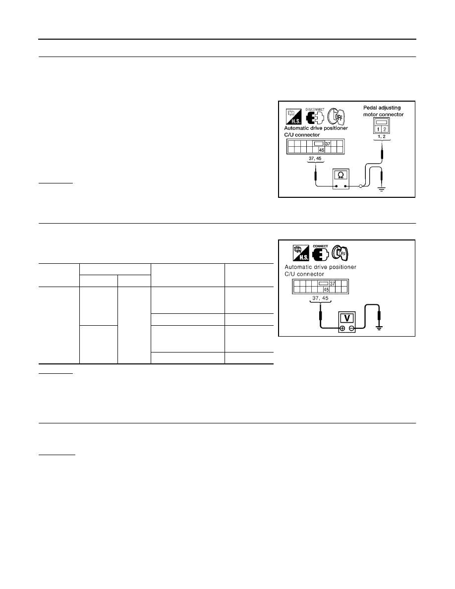
3.
CHECK PEDAL ADJUSTING MOTOR CIRCUIT HARNESS CONTINUITY
1.
Turn ignition switch OFF.
2.
Disconnect automatic drive positioner control unit and pedal adjusting motor.
3.
Check continuity between automatic drive positioner control unit connector M34 terminals 37, 45 and
pedal adjusting motor connector E109 terminals 1, 2.
4.
Check continuity between automatic drive positioner control unit
connector M34 terminals 37, 45 and ground.
OK or NG
OK
>> GO TO 4.
NG
>> Repair or replace harness.
4.
CHECK AUTOMATIC DRIVE POSITIONER CONTROL UNIT OUTPUT SIGNAL
1.
Connect the automatic drive positioner control unit and pedal adjusting motor.
2.
Check voltage between automatic drive positioner control unit
connector and ground.
OK or NG
OK
>> Replace pedal adjusting motor.
NG
>> Replace automatic drive positioner control unit.
Mirror Motor LH Circuit Check
EIS0045K
1.
CHECK DOOR MIRROR LH MECHANISM
Check the following items.
Operation malfunction caused by a foreign object caught in door mirror face edge.
OK or NG
OK
>> GO TO 2.
NG
>> Repair or replace the malfunctioning parts, and check the symptom again.
37 - 2
: Continuity should exist.
45 - 1
: Continuity should exist.
37 - Ground
: Continuity should not exist.
45 - Ground
: Continuity should not exist.
LIIA1755E
Connector
Terminals
Condition
Voltage (V)
(Approx.)
(+)
(–)
M34
37
Ground
Pedal adjusting switch
ON (FORWARD opera-
tion)
Battery voltage
Other than above
0
45
Pedal adjusting switch
ON (BACKWARD oper-
ation)
Battery voltage
Other than above
0
PIIA4806E
AUTOMATIC DRIVE POSITIONER
SE-49
C
D
E
F
G
H
J
K
L
M
A
B
SE
2005 Pathfinder
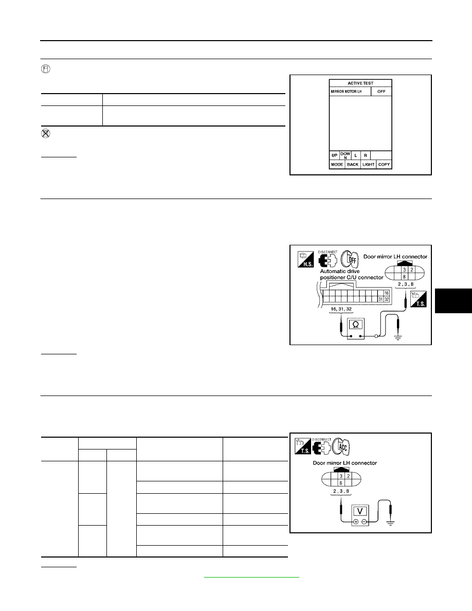
2.
CHECK FUNCTION
With CONSULT–II
Check the operation with “MIRROR MOTOR LH” in the ACTIVE
TEST.
Without CONSULT–II
GO TO 3.
OK or NG
OK
>> Mirror motor LH circuit is OK.
NG
>> GO TO 3.
3.
CHECK DOOR MIRROR MOTOR LH CIRCUIT HARNESS CONTINUITY
1.
Turn ignition switch OFF.
2.
Disconnect automatic drive positioner control unit and door mirror LH.
3.
Check continuity between automatic drive positioner control unit connector M33 terminals 16, 31, 32 and
door mirror LH connector D4 terminals 2, 3, 8.
4.
Check continuity between automatic drive positioner control unit
connector M33 terminals 16, 31, 32 and ground.
OK or NG
OK
>> GO TO 4.
NG
>> Repair or replace harness.
4.
CHECK MIRROR MOTOR SIGNAL
1.
Connect automatic drive positioner control unit.
2.
Turn ignition switch to ACC.
3.
Check voltage between door mirror LH connector and ground.
OK or NG
OK
>> Replace door mirror LH. Refer to
.
NG
>> Replace automatic drive positioner control unit.
Test item
Description
MIRROR MOTOR
LH
The mirror motor LH moves the mirror UP/DOWN and LEFT/
RIGHT by receiving the drive signal.
PIIA4784E
16 - 8
: Continuity should exist.
31 - 3
: Continuity should exist.
32 - 2
: Continuity should exist.
16 - Ground
: Continuity should not exist.
31 - Ground
: Continuity should not exist.
32 - Ground
: Continuity should not exist.
LIIA1756E
Connector
Terminals
Condition
Voltage (V)
(Approx.)
(+)
(–)
D4
3
Ground
When motor is
operated UP
1.5 - Battery voltage
Other than above
0
2
When motor is
operated LEFT
1.5 - Battery voltage
Other than above
0
8
When motor is
operated DOWN or RIGHT
1.5 - Battery voltage
Other than above
0
LIIA1758E
SE-50
AUTOMATIC DRIVE POSITIONER
2005 Pathfinder
Mirror Motor RH Circuit Check
EIS0045L
1.
CHECK DOOR MIRROR RH MECHANISM
Check the following items.
Operation malfunction caused by a foreign object caught in door mirror face edge.
OK or NG
OK
>> GO TO 2.
NG
>> Repair or replace the malfunctioning parts, and check the symptom again.
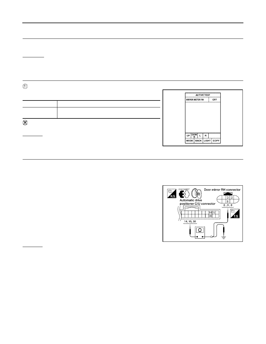
2.
CHECK FUNCTION
With CONSULT–II
Check the operation with “MIRROR MOTOR RH” in the ACTIVE
TEST.
Without CONSULT–II
GO TO 3.
OK or NG
OK
>> Mirror motor RH circuit is OK.
NG
>> GO TO 3.
3.
CHECK DOOR MIRROR RH CIRCUIT HARNESS CONTINUITY
1.
Turn ignition switch OFF.
2.
Disconnect automatic drive positioner control unit and door mirror RH connector.
3.
Check continuity between automatic drive positioner control unit connector M33 terminals 14, 15, 30 and
door mirror RH connector D107 terminals 2, 3, 8.
4.
Check continuity between automatic drive positioner control unit
connector M33 terminals 14, 15, 30 and ground.
OK or NG
OK
>> GO TO 4.
NG
>> Repair or replace harness.
Test item
Description
MIRROR MOTOR
RH
The mirror motor RH moves the mirror UP/DOWN and LEFT/
RIGHT by receiving the drive signal.
PIIA0202E
14 - 3
: Continuity should exist.
15 - 2
: Continuity should exist.
30 - 8
: Continuity should exist.
14 - Ground
: Continuity should not exist.
15 - Ground
: Continuity should not exist.
30 - Ground
: Continuity should not exist.
LIIA1759E
Нет комментариевНе стесняйтесь поделиться с нами вашим ценным мнением.
Текст