Nissan Juke (2012 year). Service Repair Manual — part 78

DIAGNOSIS SYSTEM (ECM)
EC-65
< SYSTEM DESCRIPTION >
[MR16DDT ]
C
D
E
F
G
H
I
J
K
L
M
A
EC
N
P
O
Explanation for Driving Patterns for “Misfire <Exhaust Quality Deterioration>”, “Fuel Injection System”
Driving Pattern B
EC-67, "DIAGNOSIS DESCRIPTION : Driving Pattern"
.
*1: When the same malfunction is de-
tected in two consecutive trips, MIL
will light up.
*2: MIL will turn OFF after vehicle is driv-
en 3 times (pattern B) without any
malfunctions.
*3: When the same malfunction is de-
tected in two consecutive trips, the
DTC and the freeze frame data will be
stored in ECM.
*4: The DTC and the freeze frame data
will not be displayed any longer after
vehicle is driven 80 times (pattern C)
without the same malfunction. (The
DTC and the freeze frame data still
remain in ECM.)
*5: When a malfunction is detected for
the first time, the 1st trip DTC and the
1st trip freeze frame data will be
stored in ECM.
*6: The 1st trip DTC and the 1st trip
freeze frame data will be cleared at
the moment OK is detected.
*7: When the same malfunction is de-
tected in the 2nd trip, the 1st trip
freeze frame data will be cleared.
*8: 1st trip DTC will be cleared when ve-
hicle is driven once (pattern C) with-
out the same malfunction after DTC
is stored in ECM.
JMBIA1417GB
Revision: 2011 October
2012 JUKE

EC-66
< SYSTEM DESCRIPTION >
[MR16DDT ]
DIAGNOSIS SYSTEM (ECM)
Driving Pattern C
EC-67, "DIAGNOSIS DESCRIPTION : Driving Pattern"
.
Example:
If the stored freeze frame data is as per the following:
Engine speed: 850 rpm, Calculated load value: 30%, Engine coolant temperature: 80
°
C (176
°
F)
To be satisfied with driving pattern C, the vehicle should run under the following conditions:
Engine speed: 475 – 1,225 rpm, Calculated load value: 27 – 33%, Engine coolant temperature: more than
70
°
C (158
°
F)
Relationship Between MIL, DTC, 1st Trip DTC and Driving Patterns Except For “Misfire <Exhaust
Quality Deterioration>”, “Fuel Injection System”
JMBIA1418GB
Revision: 2011 October
2012 JUKE
DIAGNOSIS SYSTEM (ECM)
EC-67
< SYSTEM DESCRIPTION >
[MR16DDT ]
C
D
E
F
G
H
I
J
K
L
M
A
EC
N
P
O
Explanation for Driving Patterns Except for “Misfire <Exhaust Quality Deterioration>”, “Fuel Injection
System”
Driving Pattern A
EC-67, "DIAGNOSIS DESCRIPTION : Driving Pattern"
.
Driving Pattern B
EC-67, "DIAGNOSIS DESCRIPTION : Driving Pattern"
.
DIAGNOSIS DESCRIPTION : Driving Pattern
INFOID:0000000007576983
CAUTION:
Always drive at a safe speed.
DRIVING PATTERN A
Driving pattern A means a trip satisfying the following conditions.
• Engine speed reaches 400 rpm or more.
• Engine coolant temperature rises by 20
°
C (36
°
F) or more after starting the engine.
• Engine coolant temperature reaches 70
°
C (158
°
F) or more.
• The ignition switch is turned from ON to OFF.
NOTE:
• When the same malfunction is detected regardless of driving conditions, reset the counter of driving pattern
A.
• When the above conditions are satisfied without detecting the same malfunction, reset the counter of driving
pattern A.
DRIVING PATTERN B
Driving pattern B means a trip satisfying the following conditions.
• Engine speed reaches 400 rpm or more.
• Engine coolant temperature reaches 70
°
C (158
°
F) or more.
• Vehicle speed of 70 – 120 km/h (44 – 75 MPH) is maintained for 60 seconds or more under the control of
closed loop.
• Vehicle speed of 30 – 60 km/h (19 – 37 MPH) is maintained for 10 seconds or more under the control of
closed loop.
• Under the closed loop control condition, the following state reaches 12 seconds or more in total: Vehicle
speed of 4 km/h (2 MPH) or less with idling condition.
• The state of driving at 10 km/h (7 MPH) or more reaches 10 minutes or more in total.
• A lapse of 22 minutes or more after engine start.
NOTE:
• Drive the vehicle at a constant velocity.
• When the same malfunction is detected regardless of driving conditions, reset the counter of driving pattern
B.
• When the above conditions are satisfied without detecting the same malfunction, reset the counter of driving
pattern B.
DRIVING PATTERN C
Driving pattern C means operating vehicle as per the following:
The following conditions should be satisfied at the same time:
Engine speed: (Engine speed in the freeze frame data)
±
375 rpm
*1: When the same malfunction is de-
tected in two consecutive trips, MIL
will light up.
*2: MIL will turn OFF after vehicle is driv-
en 3 times (pattern B) without any
malfunctions.
*3: When the same malfunction is de-
tected in two consecutive trips, the
DTC and the freeze frame data will be
stored in ECM.
*4: The DTC and the freeze frame data
will not be displayed any longer after
vehicle is driven 40 times (pattern A)
without the same malfunction.
(The DTC and the freeze frame data
still remain in ECM.)
*5: When a malfunction is detected for
the first time, the 1st trip DTC and the
1st trip freeze frame data will be
stored in ECM.
*6: 1st trip DTC will be cleared after vehi-
cle is driven once (pattern B) without
the same malfunction.
*7: When the same malfunction is de-
tected in the 2nd trip, the 1st trip
freeze frame data will be cleared.
Revision: 2011 October
2012 JUKE

EC-68
< SYSTEM DESCRIPTION >
[MR16DDT ]
DIAGNOSIS SYSTEM (ECM)
Calculated load value: (Calculated load value in the freeze frame data) x (1
±
0.1) [%]
Engine coolant temperature condition:
• When the freeze frame data shows lower than 70
°
C (158
°
F), engine coolant temperature should be lower
than 70
°
C (158
°
F).
• When the freeze frame data shows higher than or equal to 70
°
C (158
°
F), engine coolant temperature should
be higher than or equal to 70
°
C (158
°
F).
NOTE:
• When the same malfunction is detected regardless of the above vehicle conditions, reset the counter of driv-
ing pattern C.
• When the above conditions are satisfied without detecting the same malfunction, reset the counter of driving
pattern C.
• The 1st trip DTC will be cleared when C counter is counted once without the same malfunction after DTC is
stored in ECM.
DIAGNOSIS DESCRIPTION : System Readiness Test (SRT) Code
INFOID:0000000007576984
System Readiness Test (SRT) code is specified in Service $01 of SAE J1979/ISO 15031-5.
As part of an enhanced emissions test for Inspection & Maintenance (I/M), certain states require the status of
SRT be used to indicate whether the ECM has completed self-diagnosis of major emission systems and com-
ponents. Completion must be verified in order for the emissions inspection to proceed.
If a vehicle is rejected for a State emissions inspection due to one or more SRT items indicating “INCMP”, use
the information in this Service Manual to set the SRT to “CMPLT”.
In most cases the ECM will automatically complete its self-diagnosis cycle during normal usage, and the SRT
status will indicate “CMPLT” for each application system. Once set as “CMPLT”, the SRT status remains
“CMPLT” until the self-diagnosis memory is erased.
Occasionally, certain portions of the self-diagnostic test may not be completed as a result of the customer's
normal driving pattern; the SRT will indicate “INCMP” for these items.
NOTE:
The SRT will also indicate “INCMP” if the self-diagnosis memory is erased for any reason or if the ECM mem-
ory power supply is interrupted for several hours.
If, during the state emissions inspection, the SRT indicates “CMPLT” for all test items, the inspector will con-
tinue with the emissions test. However, if the SRT indicates “INCMP” for one or more of the SRT items the
vehicle is returned to the customer untested.
NOTE:
If permanent DTC is stored or MIL illuminates during the state emissions inspection, the vehicle is also
returned to the customeruntested even though the SRT indicates “CMPLT” for all test items. therefore, it is
important to check SRT (“CMPLT”), DTC (No DTCs) and permanent DTC (No permanent DTC) before the
inspection.
SRT SET TIMING
SRT is set as “CMPLT” after self-diagnosis has been performed one or more times. Completion of SRT is
done regardless of whether the result is OK or NG. The set timing is different between OK and NG results and
is shown in the table below.
Self-diagnosis result
Example
Diagnosis
Ignition cycle
←
ON
→
OFF
←
ON
→
OFF
←
ON
→
OFF
←
ON
→
All OK
Case 1
P0400
OK (1)
— (1)
OK (2)
— (2)
P0402
OK (1)
— (1)
— (1)
OK (2)
P1402
OK (1)
OK (2)
— (2)
— (2)
SRT of EGR
“CMPLT”
“CMPLT”
“CMPLT”
“CMPLT”
Case 2
P0400
OK (1)
— (1)
— (1)
— (1)
P0402
— (0)
— (0)
OK (1)
— (1)
P1402
OK (1)
OK (2)
— (2)
— (2)
SRT of EGR
“INCMP”
“INCMP”
“CMPLT”
“CMPLT”
Revision: 2011 October
2012 JUKE

DIAGNOSIS SYSTEM (ECM)
EC-69
< SYSTEM DESCRIPTION >
[MR16DDT ]
C
D
E
F
G
H
I
J
K
L
M
A
EC
N
P
O
OK: Self-diagnosis is carried out and the result is OK.
NG: Self-diagnosis is carried out and the result is NG.
—: Self-diagnosis is not carried out.
When all SRT related self-diagnoses show OK results in a single cycle (Ignition OFF-ON-OFF), the SRT will
indicate “CMPLT”.
→
Case 1 above
When all SRT related self-diagnoses show OK results through several different cycles, the SRT will indicate
“CMPLT” at the time the respective self-diagnoses have at least one OK result.
→
Case 2 above
If one or more SRT related self-diagnoses show NG results in 2 consecutive cycles, the SRT will also indicate
“CMPLT”.
→
Case 3 above
The table above shows that the minimum number of cycles for setting SRT as “INCMP” is the number one (1)
for each self-diagnosis (Case 1 & 2) or the number two (2) for one of self-diagnoses (Case 3). However, in
preparation for the state emissions inspection, it is unnecessary for each self-diagnosis to be executed twice
(Case 3) for the following reasons:
• The SRT will indicate “CMPLT” at the time the respective self-diagnoses have one (1) OK result.
• The emissions inspection requires “CMPLT” of the SRT only with OK self-diagnosis results.
• During SRT driving pattern, the 1st trip DTC (NG) is detected prior to “CMPLT” of SRT and the self-diagnosis
memory must be erased from the ECM after repair.
• If the 1st trip DTC is erased, all the SRT will indicate “INCMP”.
NOTE:
SRT can be set as “CMPLT” together with the DTC(s). Therefore, DTC check must always be carried out
prior to the state emission inspection even though the SRT indicates “CMPLT”.
DIAGNOSIS DESCRIPTION : Permanent Diagnostic Trouble Code (Permanent DTC)
INFOID:0000000007576985
Permanent DTC is defined in SAE J1979/ISO 15031-5 Service $0A.
ECM stores a DTC issuing a command of turning on MIL as a permanent DTC and keeps storing the DTC as
a permanent DTC until ECM judges that there is no presence of malfunction.
Permanent DTCs cannot be erased by using the erase function of CONSULT or Generic Scan Tool (GST) and
by disconnecting the battery to shut off power to ECM. This prevents a vehicle from passing the in-use inspec-
tion without repairing a malfunctioning part.
When not passing the in-use inspection due to more than one permanent DTC, permanent DTCs should be
erased, referring to this manual.
NOTE:
• The important items in in-use inspection are that MIL is not ON, SRT test items are set, and permanent
DTCs are not included.
• Permanent DTCs do not apply for regions that permanent DTCs are not regulated by law.
PERMANENT DTC SET TIMING
The setting timing of permanent DTC is stored in ECM with the lighting of MIL when a DTC is confirmed.
NG exists
Case 3
P0400
OK
OK
—
—
P0402
—
—
—
—
P1402
NG
—
NG
NG
(Consecutive
NG)
(1st trip)
DTC
1st trip DTC
—
1st trip DTC
DTC
(= MIL ON)
SRT of EGR
“INCMP”
“INCMP”
“INCMP”
“CMPLT”
Self-diagnosis result
Example
Diagnosis
Ignition cycle
←
ON
→
OFF
←
ON
→
OFF
←
ON
→
OFF
←
ON
→
Revision: 2011 October
2012 JUKE

EC-70
< SYSTEM DESCRIPTION >
[MR16DDT ]
DIAGNOSIS SYSTEM (ECM)
DIAGNOSIS DESCRIPTION : Malfunction Indicator Lamp (MIL)
INFOID:0000000007576986
When emission-related ECU detects a malfunction in the emission
control systems components and/or the powertrain control compo-
nents (which affect vehicle emissions), it turns on/blinks MIL to
inform the driver that a malfunction has been detected.
1.
The MIL illuminates when ignition switch is turned ON (engine is
not running).
NOTE:
Check the MIL circuit if MIL does not illuminate. Refer to
2.
When the engine is started, the MIL should go off.
NOTE:
If MIL continues to illuminate/blink, perform self-diagnoses and
inspect/repair accordingly because an emission-related ECU has detected a malfunction in the emission
control systems components and/or the powertrain control components (which affect vehicle emissions).
On Board Diagnosis Function
INFOID:0000000007576987
ON BOARD DIAGNOSIS ITEM
The on board diagnostic system has the following functions.
BULB CHECK MODE
Description
This function allows damage inspection in the MIL bulb (blown, open circuit, etc.).
Operation Procedure
1.
Turn ignition switch ON.
2.
The MIL on the instrument panel should stay ON.
If it remains OFF, check MIL circuit. Refer to
SRT STATUS MODE
Description
This function allows to read if ECM has completed the self-diagnoses of major emission control systems and
components. For SRT, refer to
EC-68, "DIAGNOSIS DESCRIPTION : System Readiness Test (SRT) Code"
.
Operation Procedure
1.
Turn ignition switch ON and wait 20 seconds.
2.
SRT status is indicated as shown blow.
• ECM continues to illuminate MIL if all SRT codes are set.
JSBIA1315ZZ
Diagnostic test mode
Function
Bulb check
MIL can be checked.
SRT status
ECM can read if SRT codes are set.
Malfunction warning
If ECM detects a malfunction, it illuminates or blinks MIL to inform the driver that a malfunction has
been detected.
Self-diagnostic results
DTCs or 1st trip DTCs stored in ECM can be read.
Accelerator pedal released po-
sition learning
ECM can learn the accelerator pedal released position. Refer to
Throttle valve closed position
learning
ECM can learn the throttle valve closed position. Refer to
.
Idle air volume learning
ECM can learn the idle air volume. Refer to
Mixture ratio self-learning value
clear
Mixture ratio self-learning value can be erased. Refer to
Revision: 2011 October
2012 JUKE

DIAGNOSIS SYSTEM (ECM)
EC-71
< SYSTEM DESCRIPTION >
[MR16DDT ]
C
D
E
F
G
H
I
J
K
L
M
A
EC
N
P
O
• ECM blinks MIL for about 10 seconds if all SRT codes are not set.
MALFUNCTION WARNING MODE
Description
In this function ECM turns on or blinks MIL when it detects a malfunction in the emission control system com-
ponents and/or the powertrain control components (which affect vehicle emissions) to inform the driver that a
malfunction has been detected.
Operation Procedure
1.
Turn ignition switch ON.
2.
Check that MIL illuminates.
If it remains OFF, check MIL circuit. Refer to
3.
Start engine and let it idle.
• For two trip detection logic diagnoses, ECM turns on MIL when it detects the same malfunction twice in
the two consecutive driving cycles.
• For 1st trip detection logic diagnoses, ECM turns on MIL when it detects a malfunction in one driving
cycle.
• ECM blinks MIL when it detects a malfunction that may damage the three way catalyst (misfire).
SELF-DIAGNOSTIC RESULTS MODE
Description
This function allows to indicate DTCs or 1st trip DTCs stored in ECM according to the number of times MIL is
blinking.
How to Set Self-diagnostic Results Mode
NOTE:
• It is better to count the time accurately with a clock.
• It is impossible to switch the diagnostic mode when an accelerator pedal position sensor circuit has a mal-
function.
• After ignition switch is turned off, ECM is always released from the “self-diagnostic results” mode.
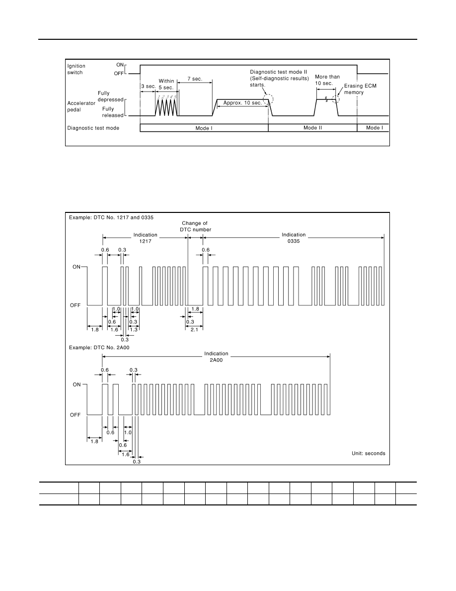
1.
Confirm that accelerator pedal is fully released, turn ignition switch ON and wait 3 seconds.
2.
Repeat the following procedure quickly five times within 5 seconds.
• Fully depress the accelerator pedal.
• Fully release the accelerator pedal.
3.
Wait 7 seconds, fully depress the accelerator pedal and keep it depressed for approx. 10 seconds until the
MIL starts blinking.
NOTE:
Do not release the accelerator pedal for 10 seconds if MIL starts blinking during this period. This blinking
is displaying SRT status and is continued for another 10 seconds.
4.
Fully release the accelerator pedal.
ECM has entered to “Self-diagnostic results” mode.
JMBIA1515GB
Revision: 2011 October
2012 JUKE
EC-72
< SYSTEM DESCRIPTION >
[MR16DDT ]
DIAGNOSIS SYSTEM (ECM)
NOTE:
Wait until the same DTC (or 1st trip DTC) appears to completely confirm all DTCs.
How to Read Self-diagnostic Results
The DTC and 1st trip DTC are indicated by the number of blinks of the MIL as shown below.
The DTC and 1st trip DTC are displayed at the same time. If the MIL does not illuminate in diagnostic test
mode I (Malfunction warning), all displayed items are 1st trip DTCs. If only one code is displayed when the MIL
illuminates in “malfunction warning” mode, it is a DTC; if two or more codes are displayed, they may be either
DTCs or 1st trip DTCs. DTC No. is same as that of 1st trip DTC. These unidentified codes can be identified by
using the CONSULT or GST. A DTC will be used as an example for how to read a code.
A particular trouble code can be identified by the number of four-digit numeral flashes per the following.
The length of time the 1,000th-digit numeral flashes on and off is 1.2 seconds consisting of an ON (0.6-sec-
onds) - OFF (0.6-seconds) cycle.
The 100th-digit numeral and lower digit numerals consist of a 0.3-seconds ON and 0.3-seconds OFF cycle.
A change from one digit numeral to another occurs at an interval of 1.0-second OFF. In other words, the later
numeral appears on the display 1.3 seconds after the former numeral has disappeared.
A change from one trouble code to another occurs at an interval of 1.8-seconds OFF.
PBIB0092E
PBIB3005E
Number
0
1
2
3
4
5
6
7
8
9
A
B
C
D
E
F
Flashes
10
1
2
3
4
5
6
7
8
9
11
12
13
14
15
16
Revision: 2011 October
2012 JUKE

DIAGNOSIS SYSTEM (ECM)
EC-73
< SYSTEM DESCRIPTION >
[MR16DDT ]
C
D
E
F
G
H
I
J
K
L
M
A
EC
N
P
O
In this way, all the detected malfunctions are classified by their DTC numbers. The DTC 0000 refers to no mal-
function. Refer to
How to Erase Self-diagnostic Results
By performing this procedure, ECM memory is erased and the following diagnostic information is erased as
well.
• Diagnostic trouble codes
• 1st trip diagnostic trouble codes
• Freeze frame data
• 1st trip freeze frame data
• System readiness test (SRT) codes
• Test values
NOTE:
Also, if a battery terminal is disconnected, ECM memory is erased and the diagnostic information as listed
above is erased. (The amount of time required for erasing may vary from a few seconds to several hours.)
1.
Turn ignition switch OFF and wait at least 10 seconds.
2.
Turn ignition switch ON.
3.
Turn ignition switch OFF and wait at least 10 seconds.
4.
Turn ignition switch ON.
5.
Set ECM in “self-diagnostic results” mode.
6.
The diagnostic information has been erased from the backup memory in the ECM.
Fully depress the accelerator pedal and keep it depressed for more than 10 seconds.
7.
Fully release the accelerator pedal, and confirm the DTC 0000 is displayed.
CONSULT Function
INFOID:0000000007576988
FUNCTION
*: The following emission-related diagnostic information is cleared when the ECM memory is erased.
• Diagnostic trouble codes
• 1st trip diagnostic trouble codes
• Freeze frame data
• 1st trip freeze frame data
• System readiness test (SRT) codes
• Test values
WORK SUPPORT MODE
Work Item
Diagnostic test mode
Function
Work support
This mode enables a technician to adjust some devices faster and more accurately by following the in-
dications on the CONSULT unit.
Self-diagnostic results
Self-diagnostic results such as 1st trip DTC, DTCs and 1st trip freeze frame data or freeze frame data
can be read and erased quickly.*
Data monitor
Input/Output data in the ECM can be read.
Active test
Diagnostic Test Mode in which CONSULT drives some actuators apart from the ECMs and also shifts
some parameters in a specified range.
DTC & SRT confirmation
The status of system monitoring tests and the self-diagnosis status/results can be confirmed.
Function test
This mode is used to inform customers when the vehicle requires periodic maintenance.
ECU part number
ECM part number can be read.
Revision: 2011 October
2012 JUKE

EC-74
< SYSTEM DESCRIPTION >
[MR16DDT ]
DIAGNOSIS SYSTEM (ECM)
*: This function is not necessary in the usual service procedure.
SELF-DIAG RESULTS MODE
Self Diagnostic Item
Regarding items of DTC and 1st trip DTC, refer to
How to Read DTC and 1st Trip DTC
DTCs and 1st trip DTCs related to the malfunction are displayed in “self-diag results”.
• When ECM detects a 1st trip DTC, “1t” is displayed for “TIME”.
• When ECM has detected a current DTC, “0” is displayed for “TIME”.
• If “TIME” is neither “0” nor “1t”, the DTC occurred in the past and ECM shows the number of times the vehi-
cle has been driven since the last detection of the DTC.
How to Erase DTC and 1st Trip DTC
NOTE:
• If the ignition switch stays ON after repair work, be sure to turn ignition switch OFF once. Wait at least 10
seconds and then turn it ON (engine stopped) again.
• If the DTC is not for CVT related items (see
), skip step 1.
1.
Erase DTC in TCM. Refer to
TM-103, "CONSULT Function (TRANSMISSION)"
.
2.
Select “ENGINE” with CONSULT.
3.
Select “SELF-DIAG RESULTS”.
4.
Touch “ERASE”. (DTC in ECM will be erased.)
Freeze Frame Data and 1st Trip Freeze Frame Data
Work item
Condition
Usage
IDLE AIR VOL LEARN
The idle air volume that keeps the engine within the specified
range is memorized in ECM.
When learning the idle air volume
EVAP SYSTEM CLOSE
Close the EVAP canister vent control valve in order to make
EVAP system close under the following conditions.
• Ignition switch ON
• Engine not running
• Ambient temperature is above 0
°
C (32
°
F)
• No vacuum and no high pressure in EVAP system
• Fuel tank temperature is more than 0
°
C (32
°
F)
• Within 10 minutes after starting “EVAP SYSTEM CLOSE”
• When trying to execute “EVAP SYSTEM CLOSE” under
the condition except above, CONSULT will discontinue it
and display appropriate instruction.
NOTE:
When starting engine, CONSULT may display “Battery
voltage is low. Charge battery”, even in using charged bat-
tery.
When detecting EVAP vapor leak
point of EVAP system
FUEL PRESSURE RELEASE
Crank a few times after engine stalls.
When releasing fuel pressure from
fuel line
TARGET IGN TIM ADJ*
Idle condition
When adjusting target ignition tim-
ing
TARGET IDLE RPM ADJ*
Idle condition
When setting target idle speed
VIN REGISTRATION
In this mode, VIN is registered in ECM.
When registering VIN in ECM
SELF-LEARNING CONT
The coefficient of self-learning control mixture ratio returns to
the original coefficient.
When clearing mixture ratio self-
learning value
G SENSOR CALIBRATION
• Park the vehicle on a flat road.
• Adjust pressure in all tires to the specified value.
Calibrates G sensor.
CLSD THL POS LEARN
• Ignition on and engine stopped.
When learning the throttle valve
closed position
Revision: 2011 October
2012 JUKE

DIAGNOSIS SYSTEM (ECM)
EC-75
< SYSTEM DESCRIPTION >
[MR16DDT ]
C
D
E
F
G
H
I
J
K
L
M
A
EC
N
P
O
*: The items are the same as those of 1st trip freeze frame data.
DATA MONITOR MODE
Monitored Item
×
: Applicable
Freeze frame data
item*
Description
DIAG TROUBLE
CODE
[PXXXX]
• The engine control component part/control system has a trouble code the is displayed as PXXXX. (Refer to
FUEL SYS-B1
• “Fuel injection system status” at the moment a malfunction is detected is displayed.
• One of the following mode is displayed.
Mode2: Open loop due to detected system malfunction
Mode3: Open loop due to driving conditions (power enrichment, deceleration enleanment)
Mode4: Closed loop - using oxygen sensor(s) as feedback for fuel control
Mode5: Open loop - has not yet satisfied condition to go to closed loop
FUEL SYS-B2
CAL/LD VALUE [%]
• The calculated load value at the moment a malfunction is detected is displayed.
COOLANT TEMP [
°
C]
or [
°
F]
• The engine coolant temperature at the moment a malfunction is detected is displayed.
L-FUEL TRM-B1 [%]
• “Long-term fuel trim” at the moment a malfunction is detected is displayed.
• The long-term fuel trim indicates much more gradual feedback compensation to the base fuel schedule than
short-term fuel trim.
L-FUEL TRM-B2 [%]
S-FUEL TRM-B1 [%]
• “Short-term fuel trim” at the moment a malfunction is detected is displayed.
• The short-term fuel trim indicates dynamic or instantaneous feedback compensation to the base fuel sched-
ule.
S-FUEL TRM-B2 [%]
ENGINE SPEED [rpm]
• The engine speed at the moment a malfunction is detected is displayed.
VEHICL SPEED
[km/h] or [mph]
• The vehicle speed at the moment a malfunction is detected is displayed.
ABSOL TH·P/S [%]
• The throttle valve opening angle at the moment a malfunction is detected is displayed.
B/FUEL SCHDL
[msec]
• The base fuel schedule at the moment a malfunction is detected is displayed.
INT/A TEMP SE [
°
C]
or [
°
F]
• The intake air temperature at the moment a malfunction is detected is displayed.
INT MANI PRES [kPa]
• These items are displayed but are not applicable to this model.
COMBUST CONDI-
TION
Monitored item
Unit
Monitor Item Selection
Description
Remarks
ECU IN-
PUT SIG-
NALS
MAIN
SIGNALS
ENG SPEED
rpm
×
×
Indicates the engine speed comput-
ed from the signal of the crankshaft
position sensor (POS) and camshaft
position sensor (PHASE).
• Accuracy becomes poor if engine
speed drops below the idle rpm.
• If the signal is interrupted while the
engine is running, an abnormal value
may be indicated.
MAS A/F SE-B1
V
×
×
The signal voltage of the mass air
flow sensor is displayed.
• When the engine is stopped, a cer-
tain value is indicated.
• When engine is running specification
range is indicated in “SPEC”.
B/FUEL SCHDL
msec
×
×
“Base fuel schedule” indicates the
fuel injection pulse width pro-
grammed into ECM, prior to any
learned on board correction.
When engine is running specification
range is indicated in “SPEC”.
Revision: 2011 October
2012 JUKE

EC-76
< SYSTEM DESCRIPTION >
[MR16DDT ]
DIAGNOSIS SYSTEM (ECM)
A/F ALPHA-B1
%
The mean value of the air-fuel ratio
feedback correction factor per cycle
is indicated.
• When the engine is stopped, a cer-
tain value is indicated.
• When engine is running specification
range is indicated in “SPEC”.
• This data also includes the data for
the air-fuel ratio learning control.
COOLAN TEMP/S
°
C or
°
F
×
×
The engine coolant temperature (de-
termined by the signal voltage of the
engine coolant temperature sensor)
is displayed.
When the engine coolant temperature
sensor is open or short-circuited, ECM
enters fail-safe mode. The engine cool-
ant temperature determined by the
ECM is displayed.
A/F SEN1 (B1)
V
×
×
The A/F signal computed from the
input signal of the air fuel ratio (A/F)
sensor 1 is displayed.
HO2S2 (B1)
V
×
×
The signal voltage of the heated ox-
ygen sensor 2 is displayed.
HO2S2 MNTR(B1)
RICH
/
LEAN
×
• Display of heated oxygen sensor
2 signal:
- RICH: means the amount of oxy-
gen after three way catalyst is rel-
atively small.
- LEAN: means the amount of oxy-
gen after three way catalyst is rel-
atively large.
When the engine is stopped, a certain
value is indicated.
VHCL SPEED SE
km/h
or
mph
×
×
The vehicle speed computed from
the vehicle speed signal sent from
combination meter is displayed.
BATTERY VOLT
V
The power supply voltage of ECM is
displayed.
ACCEL SEN 1
V
The accelerator pedal position sen-
sor signal voltage is displayed.
ACCEL SEN 2 signal is converted by
ECM internally. Thus, it differs from
ECM terminal voltage signal.
ACCEL SEN 2
TP SEN 1-B1
V
×
×
The throttle position sensor signal
voltage is displayed.
TP SEN 2-B1 signal is converted by
ECM internally. Thus, it differs from
ECM terminal voltage signal.
TP SEN 2-B1
×
×
FUEL T/TMP SE
°
C or
°
F
The fuel temperature (determined by
the signal voltage of the fuel tank
temperature sensor) is displayed.
EVAP SYS PRES
V
The signal voltage of EVAP control
system pressure sensor is dis-
played.
FUEL LEVEL SE
V
×
The signal voltage of the fuel level
sensor is displayed.
START SIGNAL
ON/
OFF
Indicates start signal status [ON/
OFF] computed by the ECM accord-
ing to the signals of engine speed
and battery voltage.
After starting the engine, [OFF] is dis-
played regardless of the starter signal.
CLSD THL POS
ON/
OFF
×
×
Indicates idle position [ON/OFF]
computed by ECM according to the
accelerator pedal position sensor
signal.
AIR COND SIG
ON/
OFF
×
×
Indicates [ON/OFF] condition of the
air conditioner switch as determined
by the air conditioner signal.
Monitored item
Unit
Monitor Item Selection
Description
Remarks
ECU IN-
PUT SIG-
NALS
MAIN
SIGNALS
Revision: 2011 October
2012 JUKE

DIAGNOSIS SYSTEM (ECM)
EC-77
< SYSTEM DESCRIPTION >
[MR16DDT ]
C
D
E
F
G
H
I
J
K
L
M
A
EC
N
P
O
PW/ST SIGNAL
ON/
OFF
×
×
[ON/OFF] condition of the power
steering system (determined by the
signal sent from EPS control unit) is
indicated.
LOAD SIGNAL
ON/
OFF
×
×
• Indicates [ON/OFF] condition from
the electrical load signal.
- ON: Rear window defogger switch
is ON and/or lighting switch is in
2nd position.
- OFF: Both rear window defogger
switch and lighting switch are
OFF.
IGNITION SW
ON/
OFF
×
×
Indicates [ON/OFF] condition from
ignition switch signal.
HEATER FAN SW
ON/
OFF
×
Indicates [ON/OFF] condition from
the heater fan switch signal.
BRAKE SW
ON/
OFF
Indicates [ON/OFF] condition from
the stop lamp switch signal.
IGN TIMING
BTD
C
×
Indicates the ignition timing comput-
ed by ECM according to the input
signals.
When the engine is stopped, a certain
value is indicated.
COMBUSTION
—
These items are displayed but are
not applicable to this model.
CAL/LD VALUE
%
“Calculated load value” indicates the
value of the current airflow divided
by peak airflow.
MASS AIRFLOW
g/s
Indicates the mass airflow computed
by ECM according to the signal volt-
age of the mass airflow sensor.
PURG VOL C/V
%
• Indicates the EVAP canister purge
volume control solenoid valve
control value computed by the
ECM according to the input sig-
nals.
• The opening becomes larger as
the value increases.
INT/V TIM(B1)
°
CA
Indicates [
°
CA] of intake camshaft
advance angle.
EXHV TIM B1
°
CA
Indicates [
°
CA] of exhaust camshaft
advance angle.
INT/V SOL(B1)
%
• The control value of the intake
valve timing control solenoid valve
(determined by ECM according to
the input signals) is indicated.
• The advance angle becomes larg-
er as the value increases.
AIR COND RLY
ON/
OFF
The air conditioner relay control con-
dition (determined by ECM accord-
ing to the input signals) is indicated.
FUEL PUMP RLY
ON/
OFF
Indicates the fuel pump relay control
condition determined by ECM ac-
cording to the input signals.
Monitored item
Unit
Monitor Item Selection
Description
Remarks
ECU IN-
PUT SIG-
NALS
MAIN
SIGNALS
Revision: 2011 October
2012 JUKE

EC-78
< SYSTEM DESCRIPTION >
[MR16DDT ]
DIAGNOSIS SYSTEM (ECM)
VENT CONT/V
ON/
OFF
• The control condition of the EVAP
canister vent control valve (deter-
mined by ECM according to the in-
put signals) is displayed.
- ON: Closed
- OFF: Open
THRTL RELAY
ON/
OFF
Indicates the throttle control motor
relay control condition determined
by the ECM according to the input
signals.
HO2S2 HTR (B1)
ON/
OFF
Indicates [ON/OFF] condition of
heated oxygen sensor 2 heater de-
termined by ECM according to the
input signals.
ALT DUTY SIG
ON/
OFF
• The control condition of the power
generation voltage variable con-
trol (determined by ECM accord-
ing to the input signals) is
indicated.
- ON: Power generation voltage
variable control is active.
- OFF: Power generation
I/P PULLY SPD
rpm
Indicates the engine speed comput-
ed from the input speed sensor sig-
nal.
VEHICLE SPEED
km/h
or
mph
The vehicle speed computed from
the vehicle speed signal sent from
TCM is displayed.
IDL A/V LEARN
YET/
CM-
PLT
• Display the condition of Idle Air
Volume Learning
- YET: Idle air volume learning has
not been performed yet.
- CMPLT: Idle air volume learning
has already been performed suc-
cessfully.
TRVL AFTER MIL
km/h
or
mph
Distance traveled while MIL is acti-
vated.
ENG OIL TEMP
°
C or
°
F
The engine oil temperature (deter-
mined by the signal voltage of the
engine oil temperature sensor) is
displayed.
A/F S1 HTR(B1)
%
• Air fuel ratio (A/F) sensor 1 heater
control value computed by ECM
according to the input signals.
• The current flow to the heater be-
comes larger as the value increas-
es.
VHCL SPEED SE
km/h
or
mph
The vehicle speed computed from
the vehicle speed signal sent from
combination meter is displayed.
SET VHCL SPD
km/h
or
mph
The preset vehicle speed is dis-
played.
MAIN SW
ON/
OFF
Indicates [ON/OFF] condition from
ASCD MAIN switch signal.
Monitored item
Unit
Monitor Item Selection
Description
Remarks
ECU IN-
PUT SIG-
NALS
MAIN
SIGNALS
Revision: 2011 October
2012 JUKE

DIAGNOSIS SYSTEM (ECM)
EC-79
< SYSTEM DESCRIPTION >
[MR16DDT ]
C
D
E
F
G
H
I
J
K
L
M
A
EC
N
P
O
CANCEL SW
ON/
OFF
Indicates [ON/OFF] condition from
CANCEL switch signal.
RESUME/ACC SW
ON/
OFF
Indicates [ON/OFF] condition from
ACCEL/RES switch signal.
SET SW
ON/
OFF
Indicates [ON/OFF] condition from
COAST/SET switch signal.
BRAKE SW1
ON/
OFF
Indicates [ON/OFF] condition from
brake pedal position switch signal.
BRAKE SW2
ON/
OFF
Indicates [ON/OFF] condition of stop
lamp switch signal.
VHCL SPD CUT
NON/
CUT
• Indicates the vehicle cruise condi-
tion.
- NON: Vehicle speed is maintained
at the ASCD set speed.
- CUT: Vehicle speed decreased to
excessively low compared with
the ASCD set speed, and ASCD
operation is cut off.
LO SPEED CUT
NON/
CUT
• Indicates the vehicle cruise condi-
tion.
- NON: Vehicle speed is maintained
at the ASCD set speed.
- CUT: Vehicle speed decreased to
excessively low, and ASCD oper-
ation is cut off.
AT OD MONITOR
ON/
OFF
Indicates [ON/OFF] condition of
CVT O/D according to the input sig-
nal from the TCM.
For M/T models, always “OFF” is dis-
played.
AT OD CANCEL
ON/
OFF
Indicates [ON/OFF] condition of
CVT O/D cancel request signal.
For M/T models, always “OFF” is dis-
played.
CRUISE LAMP
ON/
OFF
Indicates [ON/OFF] condition of
CRUISE lamp determined by the
ECM according to the input signals.
SET LAMP
ON/
OFF
NOTE:
The item is indicated, but not used.
FAN DUTY
%
Indicates a command value for cool-
ing fan. The value is calculated by
ECM based on input signals.
ALT DUTY
%
Indicates the duty ratio of the power
generation command value. The ra-
tio is calculated by ECM based on
the battery current sensor signal.
BAT CUR SEN
mV
The signal voltage of battery current
sensor is displayed.
A/F ADJ-B1
—
Indicates the correction of a factor
stored in ECM. The factor is calculat-
ed from the difference between the
target air-fuel ratio stored in ECM
and the air-fuel ratio calculated from
A/F sensor 1 signal.
P/N POSI SW
ON/
OFF
×
×
Indicates [ON/OFF] condition from
the park/neutral position (PNP) sig-
nal.
Monitored item
Unit
Monitor Item Selection
Description
Remarks
ECU IN-
PUT SIG-
NALS
MAIN
SIGNALS
Revision: 2011 October
2012 JUKE

EC-80
< SYSTEM DESCRIPTION >
[MR16DDT ]
DIAGNOSIS SYSTEM (ECM)
INT/A TEMP SE
°
C or
°
F
×
×
The intake air temperature (deter-
mined by the signal voltage of the in-
take air temperature sensor1) is
indicated.
AC PRESS SEN
V
The signal voltage from the refriger-
ant pressure sensor is displayed.
FUEL PRES SEN
MPa
Indicates the fuel rail pressure com-
puted by ECM according to the input
signals.
TURBO BST SEN
V
The turbocharger boost sensor sig-
nal voltage is displayed.
ATOM PRES SEN
V
The atmospheric pressure sensor
signal voltage is displayed.
FUEL INJ TIM
deg
Indicates the fuel injection timing
computed by ECM according to the
input signals.
FUEL INJ B1
msec
ECM-calculated injection pulse
width of the fuel injector on the Bank
1 side.
EVAP LEAK DIAG
YET/
CM-
PLT
• Indicates the condition of EVAP
leak diagnosis.
- YET: EVAP leak diagnosis has not
been performed yet.
- CMPLT: EVAP leak diagnosis has
been performed successfully.
EVAP DIAG READY
ON/
OFF
• Indicates the ready condition of
EVAP leak diagnosis.
- ON: Diagnosis has been ready
condition.
- OFF: Diagnosis has not been
ready condition.
BAT TEMP SEN
V
The signal voltage from the battery
temperature sensor is displayed.
THRTL STK CNT B1
—
NOTE:
The item is indicated, but not used.
HO2 S2 DIAG1(B1)
INC-
MP/
CM-
PLT
• Indicates DTC P0139 self-diagno-
sis (delayed response) condition.
- INCMP: Self-diagnosis is incom-
plete.
- CMPLT: Self-diagnosis is com-
plete.
HO2 S2 DIAG2(B1)
INC-
MP/
CM-
PLT
• Indicates DTC P0139 self-diagno-
sis (slow response) condition.
- INCMP: Self-diagnosis is incom-
plete.
- CMPLT: Self-diagnosis is com-
plete.
H/P FUEL PUMP
DEG
deg
Displays ECM-calculated fuel dis-
charge position of the high pressure
fuel pump.
FUEL PRES SEN V
mV
The signal voltage of FRP sensor is
displayed.
EOP SENSOR
mV
The signal voltage of EOP sensor is
displayed.
Monitored item
Unit
Monitor Item Selection
Description
Remarks
ECU IN-
PUT SIG-
NALS
MAIN
SIGNALS
Revision: 2011 October
2012 JUKE
Нет комментариевНе стесняйтесь поделиться с нами вашим ценным мнением.
Текст