Nissan Pathfinder (2010 year). Manual — part 364

EM-40
< ON-VEHICLE REPAIR >
[VQ40DE]
OIL PAN AND OIL STRAINER
b. Install new O-rings on the bottom of lower cylinder block and oil
pump.
c.
Apply a continuous bead of liquid gasket using Tool to the lower
cylinder block mating surfaces of oil pan (upper) as shown.
Use Genuine RTV Silicone Sealant or equivalent. Refer to
GI-14, "Recommended Chemical Products and Sealants"
.
CAUTION:
• For bolt holes with mark, apply liquid gasket outside
the hole.
• Apply a bead of 4.5 to 5.5 mm (0.177 to 0.217 in) in diame-
ter to area (A).
• Attaching should be done within 5 minutes after coating.
d. Install oil pan (upper).
CAUTION:
Install avoiding misalignment of both oil pan gaskets and O-rings.
• Tighten oil pan (upper) bolts in numerical order as shown.
• There are two types of bolts.
e. Tighten transmission joint bolts. Refer to
(2WD models),
(4WD models).
2. Install oil strainer to oil pan (upper).
3. Installation of the remaining components is in the reverse order of removal.
INSPECTION AFTER INSTALLATION
1. Check engine oil level and adjust as needed. Refer to
2. Start engine, and check for leaks of engine oil.
3. Stop engine and wait for 10 minutes.
4. Check engine oil level again. Refer to
PBIC2885E
Tool number
: WS39930000 (
—
)
PBIC2886E
M8
×
100 mm (3.97 in)
: 7, 11, 12, 13
M8
×
25 mm (0.98 in)
: Except the above
PBIC2887E
2010 Pathfinder

IGNITION COIL
EM-41
< ON-VEHICLE REPAIR >
[VQ40DE]
C
D
E
F
G
H
I
J
K
L
M
A
EM
N
P
O
IGNITION COIL
Exploded View
INFOID:0000000005260453
Removal and Installation
INFOID:0000000005260454
REMOVAL (LH)
1. Remove engine room cover. Refer to
EM-25, "Removal and Installation"
2. Move aside harness, harness bracket, and hoses located above ignition coil.
3. Disconnect the harness connector from the ignition coil.
4. Remove the ignition coil.
CAUTION:
Do not shock ignition coil.
INSTALLATION (LH)
Installation is in the reverse order of removal.
REMOVAL (RH)
1. Remove intake manifold collector. Refer to
EM-27, "Removal and Installation"
2. Move aside harness, harness bracket, and hoses located above ignition coil.
3. Disconnect the harness connector from the ignition coil.
4. Remove the ignition coil.
CAUTION:
Do not shock ignition coil.
INSTALLATION (RH)
Installation is in the reverse order of removal.
1.
Ignition coil
2.
Spark plug
PBIC2901E
2010 Pathfinder

EM-42
< ON-VEHICLE REPAIR >
[VQ40DE]
ROCKER COVER
ROCKER COVER
Exploded View
INFOID:0000000005260455
Removal and Installation
INFOID:0000000005260456
REMOVAL (LH)
1. Remove the engine room cover. Refer to
EM-25, "Removal and Installation"
2. Remove air duct and resonator assembly. Refer to
3. Separate engine harness removing their brackets from rocker covers.
4. Remove harness bracket from cylinder head, if necessary.
5. Disconnect and remove the intake valve timing control solenoid valve (LH bank). Refer to
6. Remove the ignition coils. Refer to
EM-41, "Removal and Installation"
.
7. Remove the PCV hoses from rocker covers.
8. Remove the oil filler cap from rocker cover (LH), if necessary.
1.
Oil filler cap
2.
PCV hose
3.
PCV valve
4.
O-ring
5.
Rocker cover (RH)
6.
PCV hose
7.
Rocker cover gasket (RH)
8.
Rocker cover gasket (LH)
9.
Rocker cover (LH)
10. PCV hose
PBIC2905E
2010 Pathfinder

ROCKER COVER
EM-43
< ON-VEHICLE REPAIR >
[VQ40DE]
C
D
E
F
G
H
I
J
K
L
M
A
EM
N
P
O
9. Loosen the rocker cover bolts with power tool in reverse order
as shown.
•
: Front
10. Remove rocker cover gaskets from rocker covers.
11. Use scraper to remove all traces of liquid gasket from cylinder head and camshaft bracket (No. 1).
CAUTION:
Do not scratch or damage the mating surface when cleaning off old liquid gasket.
INSTALLATION (LH)
1. Apply liquid gasket using Tool to joint part among rocker cover,
cylinder head and camshaft bracket (No. 1) as follows:
Use Genuine RTV Silicone Sealant or equivalent. Refer to
GI-14, "Recommended Chemical Products and Sealants"
.
NOTE:
The figure shows an example of LH side [zoomed in shows
camshaft bracket (No. 1)].
a. Apply liquid gasket to joint part of camshaft bracket (a) (No. 1)
and cylinder head.
b. Apply liquid gasket (b) to the figure (a) squarely.
2. Install new rocker cover gasket to rocker cover.
3. Install the rocker cover.
• Check to be sure rocker cover gasket is not dropped from installation groove of rocker cover.
4. Tighten the rocker cover bolts in two steps in numerical order as
shown.
•
: Front
5. Install the oil filler cap to rocker cover (LH), if removed.
6. Install the PCV hose.
AWBIA0729ZZ
Tool number
: WS39930000 (
—
)
PBIC2474E
1st step
: 1.96 N·m (0.20 kg-m, 17 in-lb)
2nd step
: 8.33 N·m (0.85 kg-m, 74 in-lb)
AWBIA0729ZZ
2010 Pathfinder

EM-44
< ON-VEHICLE REPAIR >
[VQ40DE]
ROCKER COVER
• Insert PCV hose by 25 to 30 mm (0.98 to 1.18 in) from connector end.
• When installing, be careful not to twist or come in contact with other parts.
7. Installation of the remaining components is in the reverse order of removal.
• Check engine oil level and adjust as necessary. Refer to
.
REMOVAL (RH)
1. Remove the intake manifold collector. Refer to
EM-27, "Removal and Installation"
.
CAUTION:
Perform this step when engine is cold.
2. Separate engine harness removing their brackets from rocker covers.
3. Remove harness bracket from cylinder head (RH). Refer to
EM-86, "Removal and Installation"
.
4. Disconnect and remove the intake valve timing control solenoid valve (RH bank). Refer to
5. Remove the ignition coils. Refer to
EM-41, "Removal and Installation"
.
6. Remove the PCV hoses from rocker cover.
7. Remove the PCV valve and O-ring from rocker cover (RH), if necessary.
8. Loosen the rocker cover bolts with power tool in reverse order
as shown.
•
: Front
9. Remove rocker cover gaskets from rocker covers.
10. Use scraper to remove all traces of liquid gasket from cylinder head and camshaft bracket (No. 1).
CAUTION:
Do not scratch or damage the mating surface when cleaning off old liquid gasket.
INSTALLATION (RH)
1. Apply liquid gasket using Tool to joint part among rocker cover,
cylinder head and camshaft bracket (No. 1) as follows:
Use Genuine RTV Silicone Sealant or equivalent. Refer to
GI-14, "Recommended Chemical Products and Sealants"
.
NOTE:
The figure shows an example of LH side [zoomed in shows
camshaft bracket (No. 1)].
a. Apply liquid gasket to joint part of camshaft bracket (a) (No. 1)
and cylinder head.
b. Apply liquid gasket (b) to the figure (a) squarely.
AWBIA0730ZZ
Tool number
: WS39930000 (
—
)
PBIC2474E
2010 Pathfinder

ROCKER COVER
EM-45
< ON-VEHICLE REPAIR >
[VQ40DE]
C
D
E
F
G
H
I
J
K
L
M
A
EM
N
P
O
2. Install new rocker cover gasket to rocker cover.
3. Install the rocker cover.
• Check to be sure rocker cover gasket is not dropped from installation groove of rocker cover.
4. Tighten the rocker cover bolts in two steps in numerical order as
shown.
•
: Front
5. Install new O-ring and PCV valve to rocker cover (RH), if removed.
6. Install the PCV hose.
• Insert PCV hose by 25 to 30 mm (0.98 to 1.18 in) from connector end.
• When installing, be careful not to twist or come in contact with other parts.
7. Installation of the remaining components is in the reverse order of removal.
1st step
: 1.96 N·m (0.20 kg-m, 17 in-lb)
2nd step
: 8.33 N·m (0.85 kg-m, 74 in-lb)
AWBIA0730ZZ
2010 Pathfinder

EM-46
< ON-VEHICLE REPAIR >
[VQ40DE]
FUEL INJECTOR AND FUEL TUBE
FUEL INJECTOR AND FUEL TUBE
Exploded View
INFOID:0000000005260457
Removal and Installation
INFOID:0000000005260458
CAUTION:
Do not remove or disassemble parts unless instructed as shown.
REMOVAL
WARNING:
• Put a “CAUTION FLAMMABLE” sign in the workshop.
• Be sure to work in a well ventilated area and furnish workshop with a CO
2
fire extinguisher.
• Do not smoke while servicing fuel system. Keep open flames and sparks away from the work area.
• To avoid the danger of being scalded, do not drain engine coolant when engine is hot.
1. Release the fuel pressure. Refer to
2. Disconnect the battery negative terminal. Refer to
PG-78, "Removal and Installation"
3. Remove the intake manifold collector. Refer to
EM-27, "Removal and Installation"
.
CAUTION:
Perform this step when engine is cold.
1.
Fuel tube (RH)
2.
O-ring
3.
Fuel tube (LH)
4.
Clip
5.
O-ring (blue)
6.
Fuel injector
7.
O-ring (brown)
8.
O-ring
9.
Spacer
10. Fuel damper
11. Fuel damper cap
12. Quick connector cap
13. Fuel feed hose
PBIC2957E
2010 Pathfinder
FUEL INJECTOR AND FUEL TUBE
EM-47
< ON-VEHICLE REPAIR >
[VQ40DE]
C
D
E
F
G
H
I
J
K
L
M
A
EM
N
P
O
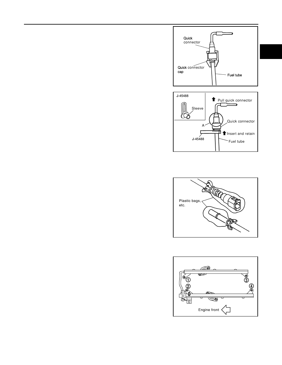
4. Disconnect the fuel quick connector on the engine side.
a. Remove quick connector cap.
b. With the sleeve side of Tool facing quick connector, install Tool
onto fuel tube.
c. Insert Tool into quick connector until sleeve contacts and goes
no further. Hold the Tool on that position.
CAUTION:
Inserting the Tool hard will not disconnect quick connector.
Hold Tool where it contacts and goes no further.
d. Pull the quick connector straight out from the fuel tube.
CAUTION:
• Pull quick connector holding it at the (A) position, as shown.
• Do not pull with lateral force applied. O-ring inside quick connector may be damaged.
• Prepare container and cloth beforehand as fuel will leak out.
• Avoid fire and sparks.
• Be sure to cover openings of disconnected pipes with
plug or plastic bag to avoid fuel leakage and entry of for-
eign materials.
5. Remove PCV hose between rocker covers (right and left banks).
6. Disconnect harness connector from fuel injector.
7. Loosen bolts in reverse order as shown, and remove fuel tube
and fuel injector assembly.
CAUTION:
Do not tilt it, or remaining fuel in pipes may flow out from
pipes.
8. Remove bolts which connects fuel tube (RH) and fuel tube (LH).
LBIA0090E
Tool number
: — (J-45488)
WBIA0295E
PBIC1899E
PBIC2902E
2010 Pathfinder
Нет комментариевНе стесняйтесь поделиться с нами вашим ценным мнением.
Текст