Nissan Murano Z51 (2008 year). Manual — part 19

AV
DIAGNOSIS SYSTEM (AV CONTROL UNIT)
AV-77
< FUNCTION DIAGNOSIS >
[BOSE AUDIO WITHOUT NAVIGATION]
C
D
E
F
G
H
I
J
K
L
M
B
A
O
P
Display Diagnosis
The tint of the color bar indication is as per the following list if RGB image signal error is detected.
Vehicle Signals
A comparison check can be made of each actual vehicle signal and
the signals recognized by the system.
Speaker Test
JSNIA0688GB
R (red) signal error
: Light blue (Cyan) tint
G (green) signal error
: Purple (Magenta) tint
B (blue) signal error
: Yellow tint
JSNIA0149GB
Diagnosis item
Display
Vehicle status
Remarks
Vehicle speed
ON
Vehicle speed > 0 km/h (0 MPH)
Changes in indication may be delayed. This is normal.
OFF
Vehicle speed = 0 km/h (0 MPH)
Parking brake
ON
Parking brake is applied.
OFF
Parking brake is released.
Lights
ON
Light switch ON
—
OFF
Light switch OFF
Ignition
ON
Ignition switch ON
—
OFF
Ignition switch in the ACC position
Reverse
ON
Shift the selector lever to the “R” po-
sition
Changes in indication may be delayed. This is normal.
OFF
Shift the selector lever to a position
other than the “R” position
Revision: 2008 October
2009 Murano

AV-78
< FUNCTION DIAGNOSIS >
[BOSE AUDIO WITHOUT NAVIGATION]
DIAGNOSIS SYSTEM (AV CONTROL UNIT)
Select “SPEAKER DIAGNOSIS” to display the Speaker Diagnosis
screen. Press “START and NEXT” to generate a test tone in a
speaker. Press “Start” to generate a test tone in the next speaker.
Press “End” to stop the test tones.
NOTE:
The frequency of test tone emitted from each speaker is as follows.
Climate Control
On-board self-diagnosis is not supported. Only CONSULT-III is supported.
Refer to
HAC-38, "CONSULT-III Function"
[without 7 inch display].
HAC-157, "CONSULT-III Function"
[with 7 inch display].
Error History
The self-diagnosis results are judged depending on whether any error occurs from when “Self-diagnosis” is
selected until the self-diagnosis results are displayed.
However, the diagnosis results are judged normal if an error has occurred before the ignition switch is turned
ON and then no error has occurred until the self-diagnosis start. Check the “Error Record” to detect any error
that may have occurred before the self-diagnosis start because of this situation.
Count up method A
• The counter resets to 0 if an error occurs when IGN switch is turned ON. The counter increases by 1 if the
condition is normal at the next IGN ON cycle.
• The counter upper limit is 39. Any counts exceeding 39 are ignored. The counter can be reset (no error
record display) with the “Delete log” switch or CONSULT-III.
Count up method B
• The counter increases by 1 if an error occurs when IGN switch is ON. The counter will not decrease even if
the condition is normal at the next IGN ON cycle.
• The counter upper limit is 50. Any counts exceeding 50 are ignored. The counter can be reset (no error
record display) with the “Delete log” switch or CONSULT-III.
Error Item
Some error items may be displayed simultaneously according to the cause. If some error items are displayed
simultaneously, the detection of the cause can be performed by the combination of display items
Tweeter
: 3 kHz
Front speaker
: 300 Hz
Rear speaker
: 1 kHz
JSNIA0150GB
Display type of occur-
rence frequency
Error history display item
Count up method A
CAN communication line, control unit (CAN), AV communication line, control unit (AV communication)
Count up method B
Other than the above
JSNIA0151GB
Revision: 2008 October
2009 Murano

AV
DIAGNOSIS SYSTEM (AV CONTROL UNIT)
AV-79
< FUNCTION DIAGNOSIS >
[BOSE AUDIO WITHOUT NAVIGATION]
C
D
E
F
G
H
I
J
K
L
M
B
A
O
P
Error item
Description
Possible malfunction factor/Action to take
CAN COMM CIRCUIT
CAN communication malfunction is detect-
ed.
Perform diagnosis with CONSULT-III, and
then repair the malfunctioning parts accord-
ing to the diagnosis results.
Refer to
CONTROL UNIT (CAN)
CAN initial diagnosis malfunction is detect-
ed.
Replace the AV control unit.
CONTROL UNIT (AV)
AV communication circuit initial diagnosis
malfunction is detected.
FLASH-ROM Error Of Control Unit
AV control unit malfunction is detected.
CAN Controller Memory Error
Front Display Connection Error
When either one of the following items are
detected:
• front display unit power supply and
ground circuits are malfunctioning.
• serial communication circuits between
AV control unit and front display unit are
malfunctioning.
• serial communication signal between AV
control unit and front display unit is mal-
functioning.
• Front display unit power supply and
ground circuits.
• Serial communication circuits between
AV control unit and front display unit.
Rear Display Connection Error
When either one of the following items are
detected:
• rear display unit power supply and
ground circuits are malfunctioning.
• serial communication circuits between
video distributor and rear display unit are
malfunctioning.
• serial communication signal between
video distributor and rear display unit is
malfunctioning.
• Rear display unit power supply and
ground circuits.
• Serial communication circuits between
video distributor and rear display unit.
Camera Control Unit Connection Error
Malfunction is detected in camera connec-
tion recognition circuit between AV control
unit and camera control unit.
Camera-connection recognition circuit be-
tween AV control unit and camera control
unit.
SAT Connection Error
When either one of the following items are
detected:
• satellite radio tuner power supply and
ground circuits are malfunctioning.
• serial communication circuits between
AV control unit and satellite radio tuner
are malfunctioning.
• serial communication or request signal
between AV control unit and satellite ra-
dio tuner is malfunctioning.
• request signal circuit between AV control
unit and satellite radio tuner is malfunc-
tioning.
• Satellite radio tuner power supply and
ground circuits.
• Serial communication circuits between
AV control unit and satellite radio tuner.
• Request signal circuit between AV con-
trol unit and satellite radio tuner.
• AV COMM CIRCUIT
• Switches Connection Error
When either one of the following items are
detected:
• multifunction switch power supply and
ground circuits are malfunctioning.
• AV communication circuits between AV
control unit and multifunction switch are
malfunctioning.
• AV communication signal between AV
control unit and multifunction switch is
malfunctioning.
• Multifunction switch power supply and
ground circuits.
• AV communication circuits between AV
control unit and multifunction switch.
Revision: 2008 October
2009 Murano

AV-80
< FUNCTION DIAGNOSIS >
[BOSE AUDIO WITHOUT NAVIGATION]
DIAGNOSIS SYSTEM (AV CONTROL UNIT)
• AV COMM CIRCUIT
• Video Distributor Connection Error
When either one of the following items are
detected:
• video distributor power supply and
ground circuits are malfunctioning.
• AV communication signal between AV
control unit and video distributor is mal-
functioning.
Video distributor power supply and ground
circuits.
• AV COMM CIRCUIT
• DVD Deck Connection Error
When either one of the following items are
detected:
• DVD player power supply and ground cir-
cuits are malfunctioning.
• AV communication signal between AV
control unit and DVD player is malfunc-
tioning.
DVD player power supply and ground cir-
cuits.
• AV COMM CIRCUIT
• Rearview Camera Connection Error
When either one of the following items are
detected:
• camera control unit power supply and
ground circuits are malfunctioning.
• AV communication signal between AV
control unit and camera control unit is
malfunctioning.
• AV communication circuits between mul-
tifunction switch and camera control unit
are malfunctioning. (Without DVD enter-
tainment system models)
• Camera control unit power supply and
ground circuits.
• AV communication circuits between mul-
tifunction switch and camera control unit.
(Without DVD entertainment system
models)
• AV COMM CIRCUIT
• iPod Connection Error
When either one of the following items are
detected:
• iPod adapter power supply and ground
circuits are malfunctioning.
• AV communication circuits between mul-
tifunction switch and iPod adapter are
malfunctioning.
• AV communication signal between AV
control unit and iPod adapter is malfunc-
tioning.
• iPod adapter power supply and ground
circuits.
• AV communication circuits between mul-
tifunction switch and iPod adapter.
• AV COMM CIRCUIT
• H/F Unit Connection Error
When either one of the following items are
detected:
• TEL adapter unit power supply and
ground circuits are malfunctioning.
• AV communication circuits between cam-
era control unit and TEL adapter unit are
malfunctioning.
• AV communication signal between AV
control unit and TEL adapter unit is mal-
functioning.
• TEL adapter unit power supply and
ground circuits.
• AV communication circuits between cam-
era control unit and TEL adapter unit.
• AV COMM CIRCUIT
• Rearview Camera Connection Error
• H/F Unit Connection Error
*
When either one of the following items are
detected:
• AV communication circuits between mul-
tifunction switch and camera control unit
are malfunctioning. (without DVD player
models)
• AV communication circuits between DVD
player and camera control unit are mal-
functioning. (with DVD player models)
• AV communication circuits between mul-
tifunction switch and camera control unit.
(without DVD player models)
• AV communication circuits between DVD
player and camera control unit. (with
DVD player models)
• AV COMM CIRCUIT
• DVD Deck Connection Error
• Rearview Camera Connection Error
• H/F Unit Connection Error
Malfunction is detected in AV communica-
tion circuits between video distributor and
DVD player.
AV communication circuits between video
distributor and DVD player.
Error item
Description
Possible malfunction factor/Action to take
Revision: 2008 October
2009 Murano

AV
DIAGNOSIS SYSTEM (AV CONTROL UNIT)
AV-81
< FUNCTION DIAGNOSIS >
[BOSE AUDIO WITHOUT NAVIGATION]
C
D
E
F
G
H
I
J
K
L
M
B
A
O
P
*: Non-equipped item is not displayed.
Camera Cont.
The two functions of “Connection Confirmation” and “Adjust Offset of Rear View Camera” are available.
CONNECTION CONFIRMATION
The steering angle sensor, reverse signal and vehicle speed sensor
can be inspected.
• AV COMM CIRCUIT
• Video Distributor Connection Error
• DVD Deck Connection Error
• Rearview Camera Connection Error
• H/F Unit Connection Error
Malfunction is detected in AV communica-
tion circuits between multifunction switch
and video distributor.
AV communication circuits between multi-
function switch and video distributor.
• AV COMM CIRCUIT
• Video Distributor Connection Error
• DVD Deck Connection Error
• Rearview Camera Connection Error
• iPod Connection Error
• H/F Unit Connection Error
Malfunction is detected in AV communica-
tion circuits between multifunction switch
and iPod adapter.
AV communication circuits between multi-
function switch and iPod adapter.
• AV COMM CIRCUIT
• Switches Connection Error
• Rearview Camera Connection Error
• iPod Connection Error
*
• H/F Unit Connection Error
*
When either one of the following items are
detected:
• AV communication circuits between AV
control unit and the branch point multi-
function switch and AV control unit are
malfunctioning.
• AV communication circuits are malfunc-
tioning.
• AV communication circuits between AV
control unit and the branch point multi-
function switch and AV control unit.
• Check and repair the short circuit in AV
communication circuits.
• AV COMM CIRCUIT
• Switches Connection Error
• Video Distributor Connection Error
• DVD Deck Connection Error
• Rearview Camera Connection Error
• iPod Connection Error
• H/F Unit Connection Error
Error item
Description
Possible malfunction factor/Action to take
JSNIA1088GB
Diagnosis item
Display
Vehicle status
Steer. Angle Sensor
ON
When steering the vehicle with ignition switch ON (remains ON until connection
mode is stopped when it is turned ON).
OFF
• Ignition switch at ACC.
• No steering with ignition switch ON.
—
Malfunction detected in camera connection recognition signal.
Reverse Sensor
ON
Selector lever is in “R” with ignition switch ON.
OFF
• Ignition switch at ACC.
• Selector lever is in position other than “R” with ignition switch ON.
—
Malfunction detected in camera-connection recognition signal.
Vehicle Speed Sensor
ON
Vehicle speed is more than 0 km/h (0 MPH) with ignition switch ON.
OFF
• Ignition switch at ACC.
• Vehicle speed is 0 km/h (0 MPH) with ignition switch ON.
—
Malfunction detected in camera connection recognition signal.
Side view Switch
—
Not used.
Revision: 2008 October
2009 Murano

AV-82
< FUNCTION DIAGNOSIS >
[BOSE AUDIO WITHOUT NAVIGATION]
DIAGNOSIS SYSTEM (AV CONTROL UNIT)
ADJUST OFFSET OF REAR VIEW CAMERA
Use this mode to adjust the guide line display position of the rear-
view monitor if necessary after removing the rear view monitor cam-
era.
Vehicle CAN Diagnosis
• CAN communication status and error counter is displayed.
• The error counter displays “OK” if any malfunction was not
detected in the past and displays “0” if a malfunction is detected. It
increases by 1 if the status is normal at the next ignition switch ON
cycle. The upper limit of the counter is 39.
• The error counter is erased if reset.
AV COMM Diagnosis
• Displays the communication status between AV control unit (mas-
ter unit) and each unit.
• The error counter displays “OK” if any malfunction was not
detected in the past and displays “0” if a malfunction is detected. It
increases by 1 if the condition is normal at the next ignition switch
ON cycle. The upper limit of the counter is 39.
• If it resets, the error counter is erased.
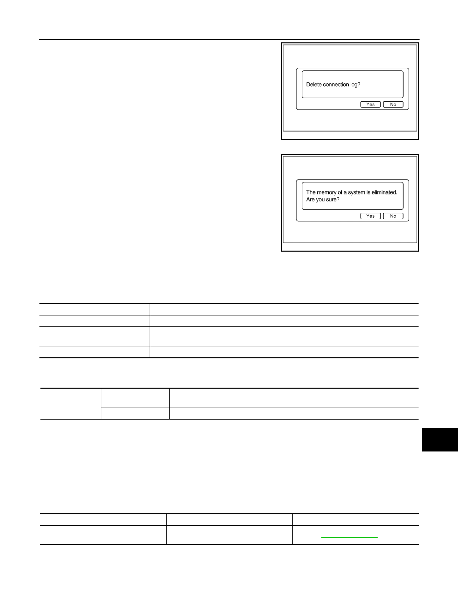
Delete Unit Connection Log
JSNIA0085GB
Items
Display (Current)
Malfunction counter
(Past)
Tx (HVAC)
OK / UNKWN
OK / 0 - 39
Rx (ECM)
OK / UNKWN
OK / 0 - 39
Rx (Cluster)
OK / UNKWN
OK / 0 - 39
Rx (BCM)
OK / UNKWN
OK / 0 - 39
Rx (HVAC)
OK / UNKWN
OK / 0 - 39
Rx (USM)
OK / UNKWN
OK / 0 - 39
JSNIA0080GB
Items
Status
(Current)
Counter
(Past)
C Tx(ITM-SW)
OK / UNKWN
OK / 0 - 39
C Rx(PrimarySW-ITM)
OK / UNKWN
OK / 0 - 39
C Rx(RearCamera-ITM)
OK / UNKWN
OK / 0 - 39
C Rx(DVD-ITM)
OK / UNKWN
OK / 0 - 39
C Rx(Video Dist-ITM)
OK / UNKWN
OK / 0 - 39
C Rx(Remote Cont-ITM)
OK / UNKWN
OK / 0 - 39
C Rx(BTHF–ITM)
OK / UNKWN
OK / 0 - 39
C Rx(iPod Adpt.–ITM)
OK / UNKWN
OK / 0 - 39
C Rx(DVDAudio-ITM)
OK / UNKWN
OK / 0 - 39
JSNIA1089GB
Revision: 2008 October
2009 Murano
AV
DIAGNOSIS SYSTEM (AV CONTROL UNIT)
AV-83
< FUNCTION DIAGNOSIS >
[BOSE AUDIO WITHOUT NAVIGATION]
C
D
E
F
G
H
I
J
K
L
M
B
A
O
P
Deletes any unit connection records and error records from the AV
control unit memory. (Clear the records of the unit that has been
removed)
Initialize Settings
Initializes the AV control unit memory.
CONSULT-III Function (MULTI AV)
INFOID:0000000003356761
CONSULT-III functions
CONSULT-III performs the following functions via communication with the AV control unit.
AV COMMUNICATION
When “AV communication” of “CAN Diag Support Monitor” is selected, the following function will be performed.
ECU IDENTIFICATION
The part number of AV control unit is displayed.
SELF DIAGNOSIS RESULT
• In CONSULT-III self-diagnosis, self-diagnosis results and error history are displayed collectively.
• The current malfunction indicates “CRNT”. The past malfunction indicates “PAST”.
• The timing is displayed as “0” if any of the error codes [U1000], [U1010], [U1300] and [U1310] is detected.
The counter increases by 1 if the condition is normal at the next ignition switch ON cycle.
Self-diagnosis Results Display Item
JSNIA0154GB
JSNIA0155GB
Diagnosis mode
Description
Ecu Identification
The part number of AV control unit can be checked.
Self Diagnostic Result
Performs a diagnosis on the AV control unit. A connection diagnosis for the communication cir-
cuit of the MULTI AV system and displays the current and past malfunctions collectively.
Data Monitor
The diagnosis of vehicle signal that is input to the AV control unit can be performed.
AV communication
AV&NAVI C/U
Displays the communication status from AV control unit to each unit as well as the error
counter.
AUDIO
Displays the AV control unit communication status and the error counter.
Error item
Description
Possible malfunction factor/Action to take
CAN COMM CIRCUIT [U1000]
CAN communication malfunction is detect-
ed.
Refer to
.
Revision: 2008 October
2009 Murano

AV-84
< FUNCTION DIAGNOSIS >
[BOSE AUDIO WITHOUT NAVIGATION]
DIAGNOSIS SYSTEM (AV CONTROL UNIT)
CONTROL UNIT (CAN) [U1010]
CAN initial diagnosis malfunction is detect-
ed.
Replace the AV control unit
CONTROL UNIT (AV) [U1310]
AV communication circuit initial diagnosis
malfunction is detected.
Cont Unit FLASH-ROM [U1200]
AV control unit malfunction is detected.
CAN CONT [U1216]
FRONT DISP CONN [U1243]
When either one of the following items are
detected:
• front display unit power supply and
ground circuits are malfunctioning.
• serial communication circuits between
AV control unit and front display unit are
malfunctioning.
• serial communication signal between AV
control unit and front display unit is mal-
functioning.
• Front display unit power supply and
ground circuits.
• Serial communication circuits between
AV control unit and front display unit.
REAR DISP CONN [U1247]
When either one of the following items are
detected:
• rear display unit power supply and
ground circuits are malfunctioning.
• serial communication circuits between
video distributor and rear display unit are
malfunctioning.
• serial communication signal between
video distributor and rear display unit is
malfunctioning.
• Rear display unit power supply and
ground circuits.
• Serial communication circuits between
video distributor and rear display unit.
CAMERA CONT CONN [U1250]
Malfunction is detected in camera connec-
tion recognition circuit between AV control
unit and camera control unit.
Camera-connection recognition circuit be-
tween AV control unit and camera control
unit.
SAT CONN [U1255]
When either one of the following items are
detected:
• satellite radio tuner power supply and
ground circuits are malfunctioning.
• serial communication circuits between
AV control unit and satellite radio tuner
are malfunctioning.
• serial communication or request signal
between AV control unit and satellite ra-
dio tuner is malfunctioning.
• request signal circuit between AV control
unit and satellite radio tuner is malfunc-
tioning.
• Satellite radio tuner power supply and
ground circuits.
• Serial communication circuits between
AV control unit and satellite radio tuner.
• Request signal circuit between AV con-
trol unit and satellite radio tuner.
• AV COMM CIRCUIT [U1300]
• SWITCH CONN [U1240]
When either one of the following items are
detected:
• multifunction switch power supply and
ground circuits are malfunctioning.
• AV communication circuits between AV
control unit and multifunction switch are
malfunctioning.
• AV communication signal between AV
control unit and multifunction switch is
malfunctioning.
• Multifunction switch power supply and
ground circuits.
• AV communication circuits between AV
control unit and multifunction switch.
• AV COMM CIRCUIT [U1300]
• VIDEO DIST CONN [U1246]
When either one of the following items are
detected:
• video distributor power supply and
ground circuits are malfunctioning.
• AV communication signal between AV
control unit and video distributor is mal-
functioning.
Video distributor power supply and ground
circuits.
Error item
Description
Possible malfunction factor/Action to take
Revision: 2008 October
2009 Murano

AV
DIAGNOSIS SYSTEM (AV CONTROL UNIT)
AV-85
< FUNCTION DIAGNOSIS >
[BOSE AUDIO WITHOUT NAVIGATION]
C
D
E
F
G
H
I
J
K
L
M
B
A
O
P
• AV COMM CIRCUIT [U1300]
• DVD DECK CONN [U1248]
When either one of the following items are
detected:
• DVD player power supply and ground cir-
cuits are malfunctioning.
• AV communication signal between AV
control unit and DVD player is malfunc-
tioning.
DVD player power supply and ground cir-
cuits.
• AV COMM CIRCUIT [U1300]
• REAR CAMERA LAN CONN [U1252]
When either one of the following items are
detected:
• camera control unit power supply and
ground circuits are malfunctioning.
• AV communication signal between AV
control unit and camera control unit is
malfunctioning.
• AV communication circuits between mul-
tifunction switch and camera control unit
is malfunctioning. (Without DVD enter-
tainment system models)
• Camera control unit power supply and
ground circuits.
• AV communication circuits between mul-
tifunction switch and camera control unit.
(Without DVD entertainment system
models)
• AV COMM CIRCUIT [U1300]
• IPod CONN [U1254]
When either one of the following items are
detected:
• iPod adapter power supply and ground
circuits are malfunctioning.
• AV communication circuits between mul-
tifunction switch and iPod adapter are
malfunctioning.
• AV communication signal between AV
control unit and iPod adapter is malfunc-
tioning.
• iPod adapter power supply and ground
circuits.
• AV communication circuits between mul-
tifunction switch unit and iPod adapter.
• AV COMM CIRCUIT [U1300]
• HAND FREE CONN [U1256]
When either one of the following items are
detected:
• TEL adapter unit power supply and
ground circuits are malfunctioning.
• AV communication circuits between cam-
era control unit and TEL adapter unit are
malfunctioning.
• AV communication signal between AV
control unit and TEL adapter unit is mal-
functioning.
• TEL adapter unit power supply and
ground circuits.
• AV communication circuits between cam-
era control unit and TEL adapter unit.
• AV communication circuits between mul-
tifunction switch and TEL adapter unit.
(without rear view camera models)
• AV COMM CIRCUIT [U1300]
• REAR CAMERA LAN CONN [U1252]
• HAND FREE CONN [U1256]
*
When either one of the following items are
detected:
• AV communication circuits between mul-
tifunction switch and camera control unit
are malfunctioning. (without DVD player
models)
• AV communication circuits between DVD
player and camera control unit are mal-
functioning. (with DVD player models)
• AV communication circuits between mul-
tifunction switch and camera control unit.
(without DVD player models)
• AV communication circuits between DVD
player and camera control unit. (with
DVD player models)
• AV COMM CIRCUIT [U1300]
• DVD DECK CONN [U1248]
• REAR CAMERA LAN CONN [U1252]
• HAND FREE CONN [U1256]
Malfunction is detected in AV communica-
tion circuits between video distributor and
DVD player.
AV communication circuits between video
distributor and DVD player.
• AV COMM CIRCUIT [U1300]
• VIDEO DIST CONN [U1246]
• DVD DECK CONN [U1248]
• REAR CAMERA LAN CONN [U1252]
• IPod CONN [U1254]
• HAND FREE CONN [U1256]
Malfunction is detected in AV communica-
tion circuits between multifunction switch
and iPod adapter.
AV communication circuits between multi-
function switch and iPod adapter.
• AV COMM CIRCUIT [U1300]
• VIDEO DIST CONN [U1246]
• DVD DECK CONN [U1248]
• REAR CAMERA LAN CONN [U1252]
• HAND FREE CONN [U1256]
Malfunction is detected in AV communica-
tion circuits between multifunction switch
and video distributor.
AV communication circuits between multi-
function switch and video distributor.
Error item
Description
Possible malfunction factor/Action to take
Revision: 2008 October
2009 Murano

AV-86
< FUNCTION DIAGNOSIS >
[BOSE AUDIO WITHOUT NAVIGATION]
DIAGNOSIS SYSTEM (AV CONTROL UNIT)
NOTE:
*: Non-equipped item is not displayed.
DATA MONITOR
ALL SIGNALS
• Displays the status of the following vehicle signals inputted into the AV control unit.
• For each signal, the actual signal can be compared the condition recognized on the system.
SELECTION FROM MENU
Allows the technician to select which vehicle signals should be displayed and displays the status of the
selected vehicle signals.
• AV COMM CIRCUIT [U1300]
• SWITCH CONN [U1240]
• IPod CONN [U1254]
*
• HAND FREE CONN [U1256]
*
When either one of the following items are
detected:
• AV communication circuits between AV
control unit and the branch point multi-
function switch.
• AV communication circuits are malfunc-
tioning.
• AV communication circuits between AV
control unit and the branch point multi-
function switch.
• Check and repair the short circuit in AV
communication circuits.
• AV COMM CIRCUIT [U1300]
• SWITCH CONN [U1240]
• VIDEO DIST CONN [U1246]
• DVD DECK CONN [U1248]
• REAR CAMERA LAN CONN [U1252]
• IPod CONN [U1254]
• HAND FREE CONN [U1256]
Error item
Description
Possible malfunction factor/Action to take
Display Item
Dis-
play
Vehicle status
Remarks
VHCL SPD SIG
On
Vehicle speed >0 km/h (0 MPH)
Changes in indication may be delayed. This is nor-
mal.
Off
Vehicle speed =0 km/h (0 MPH)
PKB SIG
On
Parking brake is applied.
Off
Parking brake is released.
ILLUM SIG
On
Light switch ON
—
Off
Light switch OFF
IGN SIG
On
Ignition switch ON
Off
Ignition switch in ACC position
REV SIG
On
Shift the selector lever to the “R” posi-
tion
Changes in indication may be delayed. This is nor-
mal.
Off
Shift the selector lever other than the
“R” position
Item to be selected
Description
VHCL SPD SIG
The same as when “ALL SIGNALS”
is selected.
PKB SIG
ILLUM SIG
IGN SIG
REV SIG
Revision: 2008 October
2009 Murano

AV
DIAGNOSIS SYSTEM (TEL ADAPTER UNIT)
AV-87
< FUNCTION DIAGNOSIS >
[BOSE AUDIO WITHOUT NAVIGATION]
C
D
E
F
G
H
I
J
K
L
M
B
A
O
P
DIAGNOSIS SYSTEM (TEL ADAPTER UNIT)
Diagnosis Description
INFOID:0000000003356762
HANDS-FREE PHONE SYSTEM ON BOARD DIAGNOSIS
During on board diagnosis the diagnosis function of TEL adapter unit starts with the operation of the steering
switch and performs the diagnosis when ignition switch ACC.
On board diagnosis item
The on board diagnosis has 3 modes: the self-diagnosis mode that performs the trouble diagnosis, the
speaker adaptation data deleting mode and the hands-free phone system initialization mode.
CAUTION:
• Perform the diagnosis with the vehicle stopped.
• Perform STEP2 if necessary.
Self-diagnosis results
Self-diagnosis mode reads out the self-diagnosis results and indicates DTC on the display.
NOTE:
• Error count is read out simultaneously when reading out the DTC name.
• The errors are read out continuously when some errors occur at the same time. The DTC displays are com-
bined and displayed. For example, DTC 01100 is displayed when DTC 01000 and DTC 00100 are indicated
at the same time.
Self-diagnosis results
The details of error count
The error count guides “0” when the error occurs. The next time it counts up “1” if it is normal with the ignition
switch ON. It continues the count up unless the initialization of hands-free phone system is performed.
STEP
MODE
Description
STEP1
Self-diagnosis
• The self-diagnosis mode performs the microphone test.
• The self-diagnosis mode also diagnoses TEL adapter unit, TEL
antenna and steering switch.
• Those results are indicated with voice guidance and displayed
on the screen.
STEP2
Speaker adaptation data deleting
The speaker adaptation data deleting mode can delete the speaker
adaptation data.
Hands-free phone system initialization
Hands-free phone system initialization mode can perform the ini-
tialization of hands-free phone system.
DTC
DTC name
Possible causes
DTC 10000
INTERNAL FAILURE
TEL adapter unit
DTC 01000
ANT. SHORT TO BATT OR OPEN
TEL antenna
DTC 00100
ANT. SHORT TO GROUND
DTC 00010
STEERING REMOTE BUTTON STUCK A
Steering switch
DTC 00001
STEERING REMOTE BUTTON STUCK B
DTC 00000
THERE ARE NO FAILURE RECORDS TO REPORT
—
Revision: 2008 October
2009 Murano

AV-88
< FUNCTION DIAGNOSIS >
[BOSE AUDIO WITHOUT NAVIGATION]
DIAGNOSIS SYSTEM (TEL ADAPTER UNIT)
FLOW CHART OF TROUBLE DIAGNOSIS
JSNIA1181GB
Revision: 2008 October
2009 Murano

AV
U1000 CAN COMM CIRCUIT
AV-89
< COMPONENT DIAGNOSIS >
[BOSE AUDIO WITHOUT NAVIGATION]
C
D
E
F
G
H
I
J
K
L
M
B
A
O
P
COMPONENT DIAGNOSIS
U1000 CAN COMM CIRCUIT
Description
INFOID:0000000003356763
CAN (Controller Area Network) is a serial communication line for real-time application. It is an on-vehicle mul-
tiplex communication line with high data communication speed and excellent error detection ability. Many elec-
tronic control units are equipped onto a vehicle, and each control unit shares information and links with other
control units during operation (not independently). In CAN communication, control units are connected with 2
communication lines (CAN-H, CAN-L) allowing a high rate of information transmission with less wiring. Each
control unit transmits/receives data but selectively reads required data only.
CAN Communication Signal Chart. Refer to
LAN-25, "CAN Communication Signal Chart"
DTC Logic
INFOID:0000000003356764
DTC DETECTION LOGIC
Diagnosis Procedure
INFOID:0000000003356765
1.
PERFORM SELF-DIAGNOSTIC
1.
Turn ignition switch ON and wait for 2 seconds or more.
2.
Check “Self Diagnostic Result” of “MULTI AV”.
Is “CAN COMM CIRCUIT” displayed?
YES
>> Refer to “LAN system”. Refer to
LAN-16, "Trouble Diagnosis Flow Chart"
NO
>> Refer to GI section. Refer to
GI-40, "Intermittent Incident"
.
DTC
Display contents of CON-
SULT-III
Diagnostic item is detected when...
Probable malfunction location
U1000
CAN COMM CIRCUIT
AV control unit is not transmitting or receiving
CAN communication signal for 2 seconds or
more.
CAN communication system.
Revision: 2008 October
2009 Murano
AV-90
< COMPONENT DIAGNOSIS >
[BOSE AUDIO WITHOUT NAVIGATION]
U1010 CONTROL UNIT (CAN)
U1010 CONTROL UNIT (CAN)
Description
INFOID:0000000003356766
Initial diagnosis of AV control unit.
DTC Logic
INFOID:0000000003356767
DTC DETECTION LOGIC
Diagnosis Procedure
INFOID:0000000003356768
1.
REPLACE AV CONTROL UNIT
When DTC U1010 is detected, replace AV control unit.
>> INSPECTION END
DTC
Display contents of CON-
SULT-III
Diagnostic item is detected when...
Probable malfunction location
U1010
CONTROL UNIT (CAN)
CAN initial diagnosis malfunction is detected.
AV control unit.
Revision: 2008 October
2009 Murano
AV
U1310 AV CONTROL UNIT
AV-91
< COMPONENT DIAGNOSIS >
[BOSE AUDIO WITHOUT NAVIGATION]
C
D
E
F
G
H
I
J
K
L
M
B
A
O
P
U1310 AV CONTROL UNIT
Description
INFOID:0000000003356769
Replace the AV control unit if this DTC is displayed. Refer to
DTC Logic
INFOID:0000000003356770
Part name
Description
AV CONTROL UNIT
• It is the master unit of the MULTI AV system, and it is connected to each control
unit by communication. It operates each system according to communication
signals from the AV control unit.
• AV control unit includes audio function and vehicle information function.
• It is connected to ECM, A/C auto amp. and combination meter via CAN com-
munication to obtain necessary information for the vehicle information function.
• It is connected to BCM via CAN communication transmitting/receiving for the
vehicle settings function.
• It inputs the illumination signals that are required for the display dimming con-
trol.
• It inputs the signals for driving status recognition (vehicle speed, reverse and
parking brake).
• The camera image signal is input from the camera control unit. The AV control
unit outputs camera image signal to the front display unit.
• BOSE amp. ON signal and sound signal are transmitted to BOSE amp.
• Power (signal VCC and inverter VCC) is transmitted to front display.
Without DVD entertainment system
• Auxiliary image and auxiliary sound signals are input from the auxiliary input
jacks.
With DVD entertainment system
• Composite image signal (auxiliary and DVD images) is input from the video
distributor.
• Sound signal (DVD and auxiliary sounds) is input from the DVD player.
DTC
Display contents of
CONSULT-III
DTC Detection Condition
Action to take
U1310
CONTROL UNIT (AV)
[U1310]
An initial diagnosis error is detected in AV communication
circuit.
Replace AV control unit.
Revision: 2008 October
2009 Murano

AV-92
< COMPONENT DIAGNOSIS >
[BOSE AUDIO WITHOUT NAVIGATION]
U1200 AV CONTROL UNIT
U1200 AV CONTROL UNIT
Description
INFOID:0000000003470017
Replace the AV control unit if this DTC is displayed. Refer to
.
DTC Logic
INFOID:0000000003356772
Part name
Description
AV CONTROL UNIT
• It is the master unit of the MULTI AV system, and it is connected to each control
unit by communication. It operates each system according to communication
signals from the AV control unit.
• AV control unit includes audio function and vehicle information function.
• It is connected to ECM, A/C auto amp. and combination meter via CAN com-
munication to obtain necessary information for the vehicle information function.
• It is connected to BCM via CAN communication transmitting/receiving for the
vehicle settings function.
• It inputs the illumination signals that are required for the display dimming con-
trol.
• It inputs the signals for driving status recognition (vehicle speed, reverse and
parking brake).
• The camera image signal is input from the camera control unit. The AV control
unit outputs camera image signal to the front display unit.
• BOSE amp. ON signal and sound signal are transmitted to BOSE amp.
• Power (signal VCC and inverter VCC) is transmitted to front display.
Without DVD entertainment system
• Auxiliary image and auxiliary sound signals are input from the auxiliary input
jacks.
With DVD entertainment system
• Composite image signal (auxiliary and DVD images) is input from the video
distributor.
• Sound signal (DVD and auxiliary sounds) is input from the DVD player.
DTC
Display contents of
CONSULT-III
DTC Detection Condition
Action to take
U1200
Cont Unit
FLASH- ROM
[U1200]
An internal malfunction is detected in AV control unit
(FLASH-ROM).
Replace AV control unit.
Revision: 2008 October
2009 Murano
Нет комментариевНе стесняйтесь поделиться с нами вашим ценным мнением.
Текст