Qashqai J11. Driveline — part 10

AWD WARNING LAMP DOES NOT TURN OFF
DLN-145
< SYMPTOM DIAGNOSIS >
[TRANSFER: TY30A]
C
E
F
G
H
I
J
K
L
M
A
B
DLN
N
O
P
AWD WARNING LAMP DOES NOT TURN OFF
Description
INFOID:0000000010288314
AWD warning lamp does not turn OFF several seconds after engine started.
Diagnosis Procedure
INFOID:0000000010288315
1.
PERFORM SELF-DIAGNOSIS
With CONSULT
Perform AWD control unit self-diagnosis.
Is any error system detected?
YES
>> Check the error system.
NO
>> GO TO 2.
2.
CHECK AWD WARNING LAMP
Perform the trouble diagnosis of the AWD warning lamp. Refer to
DLN-126, "Diagnosis Procedure"
.
Is the inspection result normal?
YES
>> GO TO 3.
NO
>> Repair or replace the malfunctioning part.
3.
CHECK AWD CONTROL UNIT POWER SUPPLY AND GROUND CIRCUIT
Perform the trouble diagnosis of the power supply and ground circuit. Refer to
.
Is the inspection result normal?
YES
>> Check each harness connector pin terminal for malfunction or disconnection.
NO
>> Repair or replace the malfunctioning part.
DLN-146
< SYMPTOM DIAGNOSIS >
[TRANSFER: TY30A]
HEAVY TIGHT-CORNER BRAKING SYMPTOM OCCURS
HEAVY TIGHT-CORNER BRAKING SYMPTOM OCCURS
Description
INFOID:0000000010288316
Heavy tight-corner braking symptom occurs when the vehicle is driven and the steering wheel is turned fully to
either side after the engine is started.
NOTE:
Light tight-corner braking symptom may occur depending on driving conditions. This is not malfunction.
Diagnosis Procedure
INFOID:0000000010288317
1.
PERFORM ECM SELF-DIAGNOSIS
With CONSULT
Perform ECM self-diagnosis.
Is any error system detected?
YES
>> Check the error system.
NO
>> GO TO 2.
2.
PERFORM SELF-DIAGNOSIS
With CONSULT
Perform AWD control unit self-diagnosis.
Is DTC “U1000” detected?
YES
>> CAN specification chart. Refer to
LAN-24, "Trouble Diagnosis Flow Chart"
NO
>> GO TO 3.
3.
CHECK AWD SOLENOID
Perform the trouble diagnosis of the AWD solenoid. Refer to
DLN-113, "Diagnosis Procedure"
.
Is the inspection result normal?
YES
>> GO TO 4.
NO
>> Repair or replace the malfunctioning part.
4.
CHECK ELECTRIC CONTROLLED COUPLING
1.
Turn the ignition switch OFF.
2.
Set the transaxle to neutral. Release the parking brake.
3.
Lift up the vehicle.
4.
Rotate the propeller shaft by hand.
5.
Hold rear wheel of right and left lightly.
Does rear wheel rotate?
YES
>> Replace electric controlled coupling for mechanical malfunction (clutch sticking etc.). Refer to
NO
>> Check each harness connector pin terminal for disconnection.
VEHICLE DOES NOT ENTER AWD MODE
DLN-147
< SYMPTOM DIAGNOSIS >
[TRANSFER: TY30A]
C
E
F
G
H
I
J
K
L
M
A
B
DLN
N
O
P
VEHICLE DOES NOT ENTER AWD MODE
Description
INFOID:0000000010288318
Vehicle does not enter AWD mode even though AWD warning lamp turned to OFF.
Diagnosis Procedure
INFOID:0000000010288319
1.
CHECK AWD WARNING LAMP
Turn the ignition switch ON.
Does AWD warning lamp turn ON?
YES
>> GO TO 2.
NO
>> Go to
DLN-144, "Diagnosis Procedure"
.
2.
PERFORM SELF-DIAGNOSIS
With CONSULT
Perform AWD control unit self-diagnosis.
Is DTC “U1000” detected?
YES
>> CAN specification chart. Refer to
LAN-24, "Trouble Diagnosis Flow Chart"
NO
>> GO TO 3.
3.
CHECK AWD SOLENOID
Perform the trouble diagnosis of the AWD solenoid. Refer to
DLN-113, "Diagnosis Procedure"
.
Is the inspection result normal?
YES
>> GO TO 4.
NO
>> Repair or replace the malfunctioning part.
4.
CRUISE TEST
Drive the vehicle for a period of time.
Does any symptom occur?
YES
>> Replace electric controlled coupling for mechanical malfunction (mechanical engagement of
clutch is not possible). Refer to
NO
>> Check each harness connector pin terminal for disconnection.
DLN-148
< SYMPTOM DIAGNOSIS >
[TRANSFER: TY30A]
AWD WARNING LAMP BLINKS QUICKLY
AWD WARNING LAMP BLINKS QUICKLY
Description
INFOID:0000000010288320
While driving, AWD warning lamp blinks 2 times in 1 second and it turns OFF after 1 minute.
• This symptom protects drive train parts when a heavy load is applied to the electric controlled coupling and
multiple disc clutch temperature increases. Also, optional distribution of torque sometimes becomes rigid
before lamp blinks quickly. Both cases are not malfunction.
• When this symptom occurs, stop vehicle and allow it to idle for some times. Blinking will stop and system will
be restored.
AWD WARNING LAMP BLINKS SLOWLY
DLN-149
< SYMPTOM DIAGNOSIS >
[TRANSFER: TY30A]
C
E
F
G
H
I
J
K
L
M
A
B
DLN
N
O
P
AWD WARNING LAMP BLINKS SLOWLY
Description
INFOID:0000000010288321
AWD warning lamp blinks at approximately 2 seconds intervals while driving.
Diagnosis Procedure
INFOID:0000000010288322
1.
CHECK TIRE
Check the following.
• Tire pressure
• Wear condition
• Longitudinal tire size (There is no difference between longitudinal tires.)
Is the inspection result normal?
YES
>> GO TO 2.
NO
>> Drive at vehicle speed of 20 km/h (12 MPH) or more for 5 seconds or more after repairing or
replacing damaged parts. (Initialize improper size tire information.)
2.
CHECK INPUT SIGNAL OF TIRE DIAMETER
With CONSULT
1.
Start engine.
2.
Drive at 20 km/h (12 MPH) or more for approx. 200 seconds.
3.
Check “DIS-TIRE MONI” of AWD control unit CONSULT “DATA MONITOR”.
Does the item on “DATA MONITOR” indicate “0 - 4 mm”?
YES
>> INSPECTION END
NO
>> GO TO 3.
3.
TERMINAL INSPECTION
Check AWD control unit harness connector for disconnection.
Is the inspection result normal?
YES
>> Replace AWD control unit. Refer to
NO
>> Repair or replace the malfunctioning part.
DLN-150
< SYMPTOM DIAGNOSIS >
[TRANSFER: TY30A]
NORMAL OPERATING CONDITION
NORMAL OPERATING CONDITION
Description
INFOID:0000000010288323
While driving, AWD warning lamp blinks 2 times in 1 second and it turns OFF after 1 minute.
• This symptom protects drive train parts when a heavy load is applied to the electric controlled coupling and
multiple disc clutch temperature increases. Also, optional distribution of torque sometimes becomes rigid
before lamp blinks quickly. Both cases are not malfunction.
• When this symptom occurs, stop vehicle and allow it to idle for some times. Blinking will stop and system will
be restored.

NOISE, VIBRATION AND HARSHNESS (NVH) TROUBLESHOOTING
DLN-151
< SYMPTOM DIAGNOSIS >
[TRANSFER: TY30A]
C
E
F
G
H
I
J
K
L
M
A
B
DLN
N
O
P
NOISE, VIBRATION AND HARSHNESS (NVH) TROUBLESHOOTING
NVH Troubleshooting Chart
INFOID:0000000010288324
M/T MODELS
Use the chart below to help you find the cause of the symptom. The numbers indicate the order of the inspec-
tion. If necessary, repair or replace these parts.
Reference
SUSPECTED PARTS
(Possible cause)
TRANSF
ER OIL (Level l
o
w)
TRANSF
ER OIL (W
rong)
T
R
ANSFER OI
L (L
ev
el
to
o h
ig
h
)
LIQUID GASKET
(Damaged)
O-RING (W
orn
or
da
ma
ge
d)
OIL SEAL (W
orn or
damaged)
GEAR (W
o
rn o
r da
m
a
g
ed)
BEAR
ING
(W
orn
o
r
da
ma
ge
d)
Symptom
Noise
1
2
3
3
3
Transfer oil leakage
3
1
2
2
2

DLN-152
< PERIODIC MAINTENANCE >
[TRANSFER: TY30A]
TRANSFER OIL
PERIODIC MAINTENANCE
TRANSFER OIL
Inspection
INFOID:0000000010288332
OIL LEAKAGE
Check transfer surrounding area (oil seal, drain plug, filler plug, and transfer case, etc.) for oil leakage.
OIL LEVEL
1.
Remove filler plug (1) and gasket. Then check that oil is filled up
(A) from mounting hole for the filler plug.
2.
Before installing filler plug, set a new gasket. Install filler plug on
transfer and tighten to the specified torque. Refer to
CAUTION:
Never reuse gaskets.
Draining
INFOID:0000000010288333
1.
Run the vehicle to warm up the transfer unit sufficiently.
2.
Stop the engine and remove drain plug (1) and gaskets to drain
the transfer oil.
CAUTION:
Never remove tooth contact test hole plug (2).
3.
Before installing drain plug, set a new gasket. Install drain plug
on transfer and tighten to the specified torque. Refer to
CAUTION:
Never reuse gaskets.
Refilling
INFOID:0000000010288334
1.
Remove filler plug (1) and gasket. Then fill oil up to mounting
hole (A) for the filler plug.
CAUTION:
Carefully fill the oil. (Fill up for approximately 3 minutes.)
2.
Leave the vehicle for 3 minutes. Then check oil level again.
3.
Before installing filler plug, set a new gasket. Install filler plug on
transfer and tighten to the specified torque. Refer to
.
CAUTION:
Never reuse gasket.
SDIA3060J
SDIA3059J
Oil grade and viscosity
: Refer to
.
Oil capacity
: Refer to
.
SDIA3060J

AWD CONTROL UNIT
DLN-153
< REMOVAL AND INSTALLATION >
[TRANSFER: TY30A]
C
E
F
G
H
I
J
K
L
M
A
B
DLN
N
O
P
REMOVAL AND INSTALLATION
AWD CONTROL UNIT
Exploded View
INFOID:0000000010471495
Removal and Installation
INFOID:0000000010471496
REMOVAL
1.
Remove luggage side lower finisher (LH). Refer to
.
2.
Disconnect AWD control unit harness connector.
3.
Remove AWD control unit bolts (
).
NOTE:
AWD control unit is located on the back side of body panel.
4.
Remove AWD control unit.
INSTALLATION
Installation is in the reverse order of removal.
CAUTION:
• Do not drop or shock AWD control unit.
• When replacing AWD control unit, perform writing unit characteristic. Refer to
AWD control unit
: Vehicle front
: N·m (kg-m, in-lb)
JSDIA5368GB
: Front
AWDIA1154ZZ

DLN-154
< REMOVAL AND INSTALLATION >
[TRANSFER: TY30A]
AWD MODE SWITCH
AWD MODE SWITCH
Exploded View
INFOID:0000000010464154
Removal and Installation
INFOID:0000000010464155
REMOVAL
1.
Remove instrument lower panel LH. Refer to
2.
Disconnect AWD lock switch harness connector (A).
3.
Remove AWD lock switch from lower switch bracket (2).
INSTALLATION
Install in the reverse order of removal.
1.
Instrument lower panel LH
2.
AWD lock switch
Front
Pawl
ALDIA0506ZZ
: Pawls
AWDIA1151ZZ

TRANSFER ASSEMBLY
DLN-155
< UNIT REMOVAL AND INSTALLATION >
[TRANSFER: TY30A]
C
E
F
G
H
I
J
K
L
M
A
B
DLN
N
O
P
UNIT REMOVAL AND INSTALLATION
TRANSFER ASSEMBLY
Exploded View
INFOID:0000000010288345
Removal and Installation
INFOID:0000000010288346
REMOVAL
1.
Remove the exhaust front tube. Refer to
2.
Separate the rear propeller shaft. Refer to
3.
Remove right side drive shaft and support bearing bracket. Refer to
.
4.
Remove the diesel particle filter. Refer to
5.
Remove the gusset.
6.
Remove the rear torque rod. Refer to
.
1.
Gusset
2.
Transfer assembly
3.
O-ring (outer)
: Vehicle front
: Apply multi-purpose grease.
Refer to
for symbols not described on the above.
JSDIA0267GB

DLN-156
< UNIT REMOVAL AND INSTALLATION >
[TRANSFER: TY30A]
TRANSFER ASSEMBLY
7.
Remove the mounting bolts (
) of transaxle assembly and
transfer assembly.
CAUTION:
Never remove the mounting bolts (
) of adapter case.
8.
Remove transfer assembly from the vehicle.
CAUTION:
• Never damage ring gear shaft.
• Never damage air breather hose.
9.
Remove O-ring (outer) from the transfer assembly.
INSTALLATION
Note the following, and install in the reverse order of removal.
• Apply multi-purpose grease lightly and evenly onto an O-ring (outer), and install it to the transfer assembly.
CAUTION:
Never reuse O-ring (outer).
• Install mounting bolts according to the standard below when install-
ing transfer assembly to the transaxle assembly.
• Check oil level and check for oil leakage after installation. Refer to
.
SDIA3225J
Bolt symbol
A
B
Installation direction
Transfer
⇒
Transaxle
Transaxle
⇒
Transfer
SDIA3070J

ADAPTER CASE
DLN-157
< UNIT DISASSEMBLY AND ASSEMBLY >
[TRANSFER: TY30A]
C
E
F
G
H
I
J
K
L
M
A
B
DLN
N
O
P
UNIT DISASSEMBLY AND ASSEMBLY
ADAPTER CASE
Exploded View
INFOID:0000000010288347
1.
Adapter case oil seal (outer)
2.
O-ring (outer)
3.
Adapter case oil seal (inner)
4.
Adapter case
5.
O-ring (inner)
6.
Ring gear shaft
7.
Ring gear adjusting shim
(adapter case side)
8.
Ring gear shaft bearing
(adapter case side)
9.
Ring gear
10. Ring gear nut
11.
Ring gear shaft bearing
(transfer case side)
12. Ring gear adjusting shim
(transfer case side)
13. Transfer case
14. Air breather hose
15. Air breather tube
16. Gasket
17. Filler plug
18. Drain plug
19. Plug
20. Drive pinion
21. Drive pinion adjusting shim
22. Drive pinion bearing (front side)
23. Collapsible spacer
24. Drive pinion bearing (rear side)
25. Drive pinion oil seal
26. Companion flange
27. Lock nut
A: Oil seal lip
: Apply gear oil.
: Apply multi-purpose grease.
JSDIA0319GB

DLN-158
< UNIT DISASSEMBLY AND ASSEMBLY >
[TRANSFER: TY30A]
ADAPTER CASE
Disassembly
INFOID:0000000010288348
1.
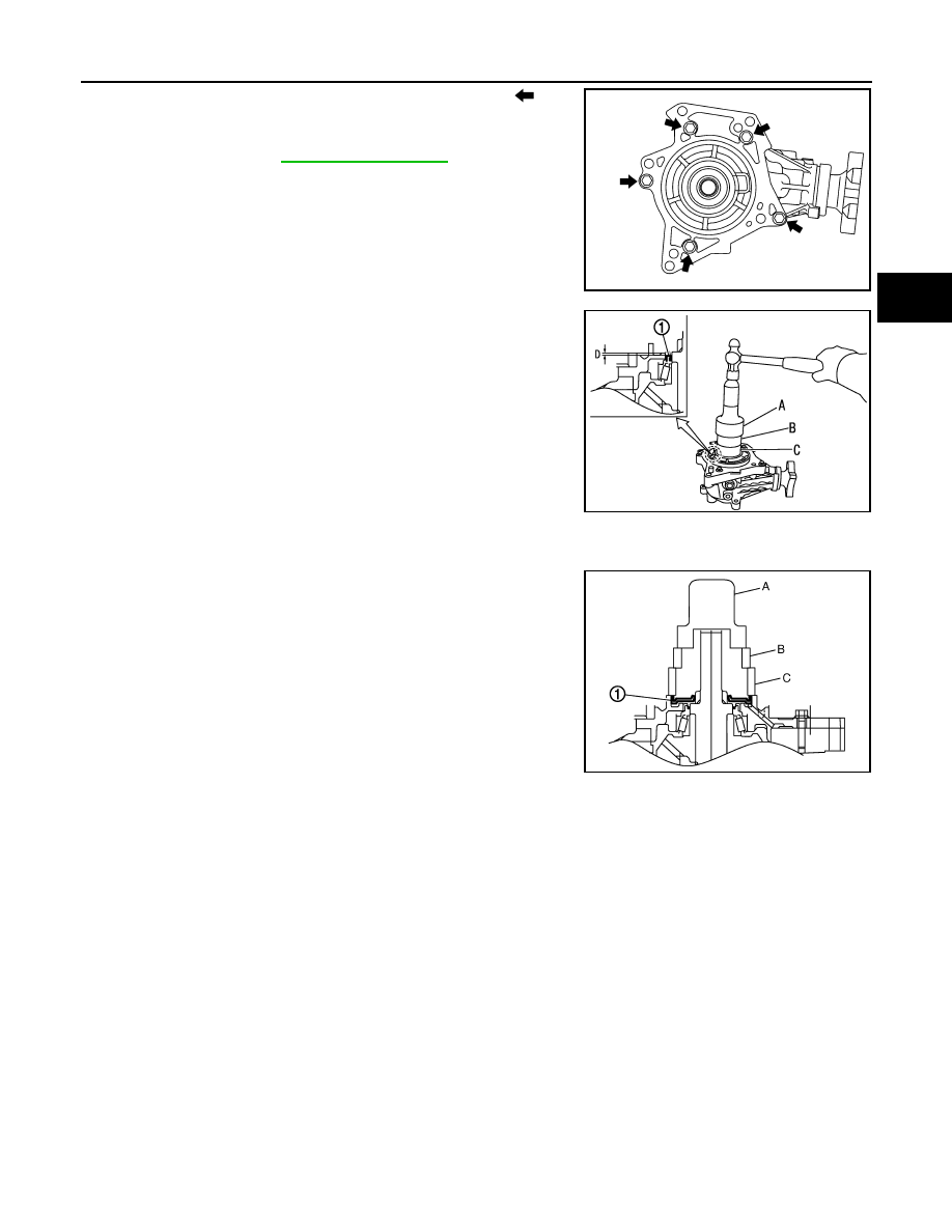
Remove O-ring (outer) from adapter case.
2.
Remove adapter case mounting bolts (
).
3.
Lightly tap adapter case with a plastic hammer to remove
adapter case.
4.
Remove O-ring (inner) from adapter case.
5.
Remove adapter case oil seal (outer/inner) with a screwdriver.
CAUTION:
Be careful not to damage adapter case.
Assembly
INFOID:0000000010288349
1.
Install O-ring (inner) to adapter case.
CAUTION:
• Never reuse O-ring (inner).
• Apply multi-purpose grease to O-ring (inner).
2.
Install adapter case to the transfer case.
: Apply anti-corrosive oil.
: Apply Genuine Liquid Gasket, Three Bond 1215 or equivalent.
Refer to
for symbols not described on the above.
SDIA3076J
JSDIA0252ZZ
SDIA3078J
ADAPTER CASE
DLN-159
< UNIT DISASSEMBLY AND ASSEMBLY >
[TRANSFER: TY30A]
C
E
F
G
H
I
J
K
L
M
A
B
DLN
N
O
P
3.
Apply anti-corrosive oil onto threads and seats of bolts (
), and
tighten with the specified torque.
4.
Check backlash, tooth contact, total preload and companion
flange runout. Refer to
CAUTION:
Measure the total preload without the adapter case oil seal
(outer/inner).
5.
Install adapter case oil seal (inner) (1) to the adapter case with
drifts.
CAUTION:
• Never reuse oil seal.
• Apply multi-purpose grease onto oil seal lips, and gear oil
onto the circumference.
• Install adapter case oil seal (inner) in the direction shown in the figure.
6.
Install adapter case oil seal (outer) (1) to the adapter case with
drifts so that it becomes flush with adapter case end surface.
CAUTION:
• Never reuse oil seal.
• Apply multi-purpose grease onto oil seal lips, and gear oil
onto the circumference.
• Install adapter case oil seal (outer) in the direction shown
in the figure.
7.
Install O-ring (outer) to the adapter case.
Inspection After Disassembly
INFOID:0000000010288350
Check items below. If necessary, replace them with new ones.
CASE
Check the bearing mounting surface for wear, cracks and damages.
SDIA3076J
A
: Drift (SST: ST30720000)
B
: Drift (SST: ST27861000)
C
: Drift (commercial service tool)
Dimension “D”
: 0 – 1.0 mm
A
: Drift (SST: ST30720000)
B
: Drift (SST: ST27861000)
C
: Drift (commercial service tool)
JSDIA0259ZZ
JSDIA0214ZZ

DLN-160
< UNIT DISASSEMBLY AND ASSEMBLY >
[TRANSFER: TY30A]
RING GEAR SHAFT
RING GEAR SHAFT
Exploded View
INFOID:0000000010288355
1.
Adapter case oil seal (outer)
2.
O-ring (outer)
3.
Adapter case oil seal (inner)
4.
Adapter case
5.
O-ring (inner)
6.
Ring gear shaft
7.
Ring gear adjusting shim
(adapter case side)
8.
Ring gear shaft bearing
(adapter case side)
9.
Ring gear
10. Ring gear nut
11.
Ring gear shaft bearing
(transfer case side)
12. Ring gear adjusting shim
(transfer case side)
13. Transfer case
14. Air breather hose
15. Air breather tube
16. Gasket
17. Filler plug
18. Drain plug
19. Plug
20. Drive pinion
21. Drive pinion adjusting shim
22. Drive pinion bearing (front side)
23. Collapsible spacer
24. Drive pinion bearing (rear side)
25. Drive pinion oil seal
26. Companion flange
27. Lock nut
A: Oil seal lip
: Apply gear oil.
: Apply multi-purpose grease.
: Apply anti-corrosive oil.
JSDIA0319GB
Нет комментариевНе стесняйтесь поделиться с нами вашим ценным мнением.
Текст