Nissan Primera P12. Manual — part 159
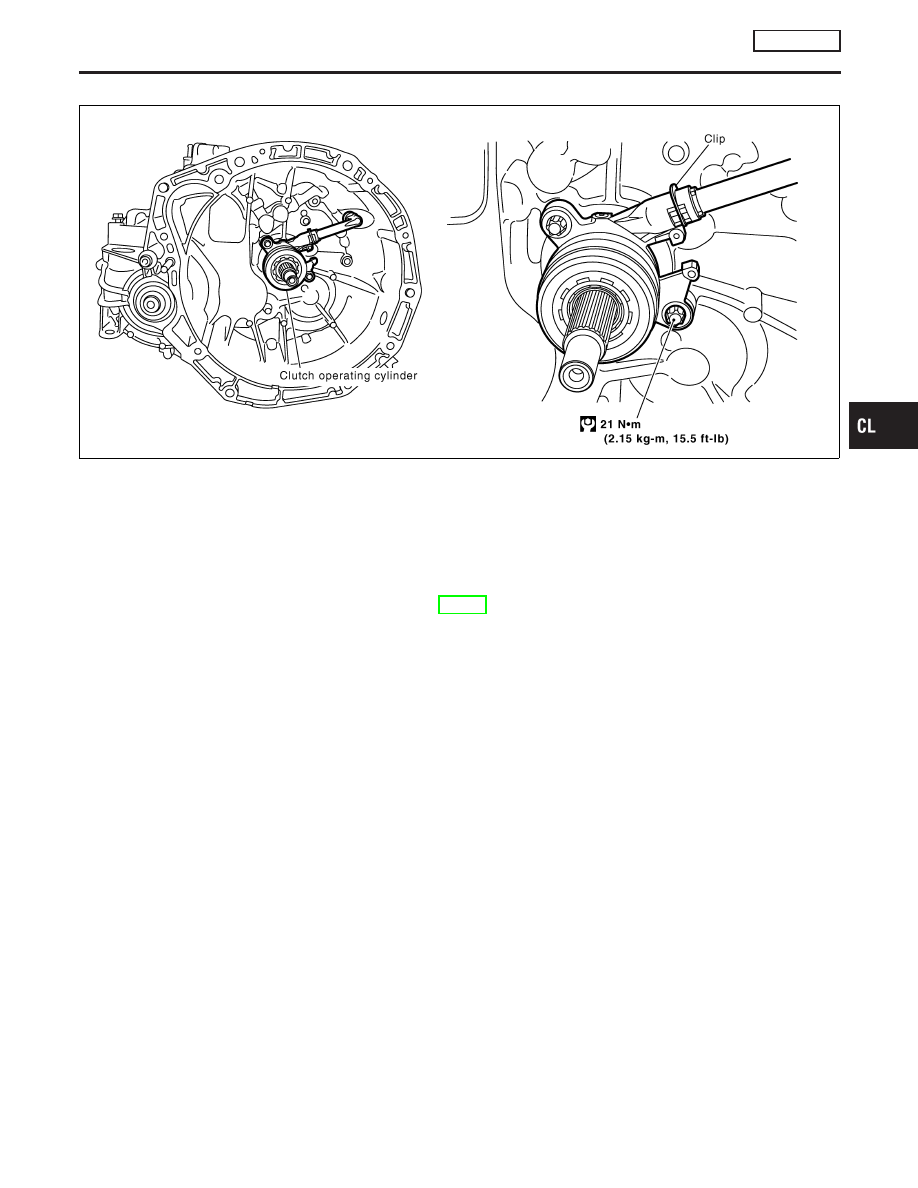
Components
NOCL0051
YCL077
Removal and Installation
NOCL0052
CAUTION:
Be careful not to splash brake fluid on painted areas; it may
cause paint damage. It brake fluid is splashed on painted
areas, wash it way with water immediately.
Refer to MT-10, “REMOVAL AND INSTALLATION”.
Inspection
NOCL0053
NOTE:
I
Cannot disassemble operating cylinder and release bearing
because they are integral parts. Replace them as an assem-
bly.
Inspect for the following, and replace parts if necessary
I
Operating cylinder: damage, foreign material, wear or pinholes
on the cylinder outer surface.
I
Release bearing: damage, incorrect rotation direction, or has
poor aligning function, and dust seal is deformed or cracked.
GI
MA
EM
LC
EC
FE
MT
AT
AX
SU
BR
ST
RS
BT
HA
SC
EL
IDX
CLUTCH RELEASE MECHANISM
RS6F93R
Components
CL-13
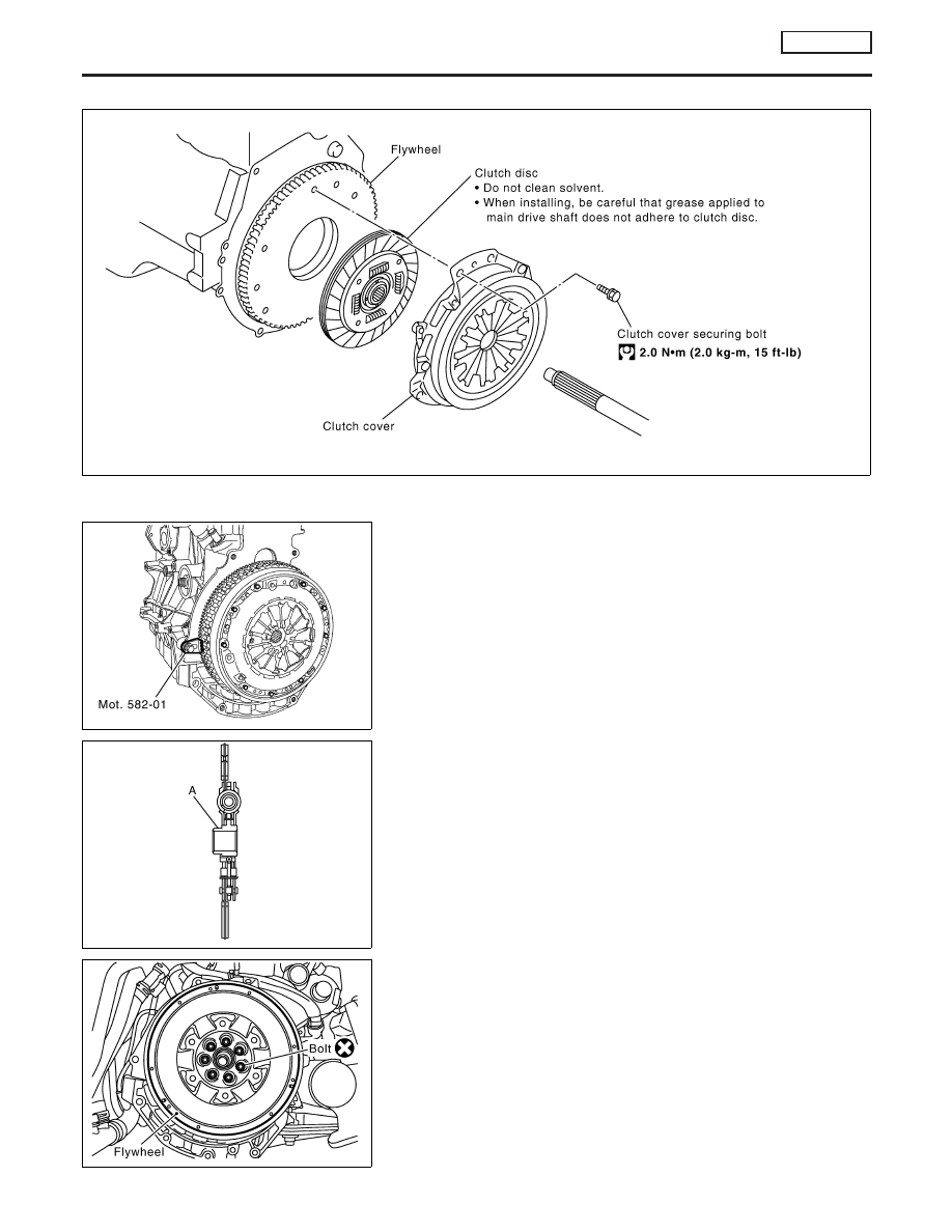
Components
NOCL0055
YCL032
YCL078
Inspection
NOCL0056
CLUTCH DISC
NOCL0056S01
Install flywheel fixing tool (SST: Mot. 582-01), and then remove
clutch cover and clutch disc.
YCL034
Check clutch disc as follows;
I
The hubs of the clutch discs are nickle plated to improve their
sliding performance.
I
Clean the splines of the clutch shaft and install the assembly
without lubricant.
I
Degrease the friction face of the flywheel.
I
Install the clutch disc [offset (A) from the hub on the flywheel
side].
YCL079
FLYWHEEL
NOCL0056S03
Replace the flywheel if it has been damaged.
CAUTION:
I
Reworking on the clutch face is not permitted.
I
Clean the threads of the flywheel mounting bolts on the
crankshaft.
I
Degrease the bearing face of the flywheel on the crank-
shaft.
I
Apply the new flywheel mounting bolts using “Loctite
FRENETANCH” or equivalent.
CLUTCH DISC, CLUTCH COVER AND FLYWHEEL
RS6F93R
Components
CL-14
Installation
NOCL0057
1.
Lock the flywheel with tool KV113B0060 (Mot. 582-01) or
KV113B0410 (Mot. 1677) depending on the cylinder block
(large or small side).
2.
Install the flywheel, tightening the new bolts to a torque of 30
N·m (3.1 kg-m, 22 ft-lb), then tighten to an angle of 56°
±
6° for
a double mass flywheel 55 N·m (5.6 kg-m, 41 ft-lb) for a stan-
dard flywheel.
CAUTION:
Use an angle wrench (special service tool) to check tightening
angle. Do not make judgment by visual inspection.
MBIB0759E
3.
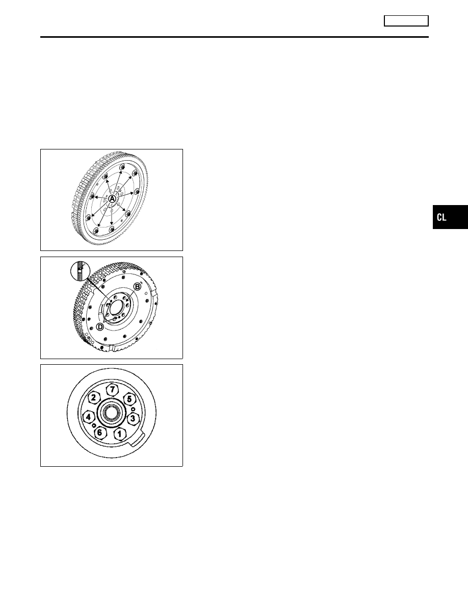
Flexible flywheel:
NOTE:
Under no circumstances should bolts (A) be removed.
MBIB0838E
NOTE:
Install the flywheel without its shim (B) is strictly prohibited, the
shim is usually joined to flexplate (C) (see the diagram opposite)
by two pins (D).
MBIB0839E
4.
It is essential to replace the flywheel mounting bolts.
I
Tighten the engine flywheel bolts in the numerical order as
shown to a torque of 65 N·m (6.6 kg-m, 48 ft-lb).
5.
Proceed in the reverse order to removal.
6.
Install the clutch, tightening the bolts to a torque of 20 N·m (2.0
kg-m, 15 ft-lb).
7.
Withdraw the flywheel immobilizer KV113B0060 (Mot. 582-01)
or KV113B0410 (Mot. 1677).
GI
MA
EM
LC
EC
FE
MT
AT
AX
SU
BR
ST
RS
BT
HA
SC
EL
IDX
CLUTCH DISC, CLUTCH COVER AND FLYWHEEL
RS6F93R
Installation
CL-15

Clutch Control System
NOCL0034
Type of clutch control
Hydraulic
Clutch Master Cylinder
NOCL0035
Unit: mm (in)
Engine
F9Q
Inner diameter
17.46 (11/16)
Clutch Operating Cylinder
NOCL0036
Unit: mm (in)
Inner diameter
19.05 (3/4)
Clutch Disc
NOCL0038
Unit: mm (in)
Engine
F9Q
Model
—
Facing size (Outer dia.
×
inner dia.
×
thickness)
—
Thickness of disc assembly with load
—
Wear limit of facing surface to rivet head
—
Wearing thickness of facing
—
Runout limit of facing
—
Distance of runout check point (from the hub center)
—
Maximum backlash of spline (at outer edge disc)
—
Clutch Cover
NOCL0039
Unit: mm (in)
Engine
F9Q
Model
—
Full-load
—
Uneven limit of diaphragm spring toe height
—
Clutch Pedal
NOCL0040
Unit: mm (in)
Pedal strokes “S”*
140 - 150 (5.512 - 5.906)
Pedal free play “A”
1 - 3 (0.039 - 0.118)
*: Measured from surface of dash lower panel to surface of pedal pad
SERVICE DATA AND SPECIFICATIONS (SDS)
Clutch Control System
CL-16
Нет комментариевНе стесняйтесь поделиться с нами вашим ценным мнением.
Текст