Nissan Primera P12. Manual — part 587
LT-58
TURN SIGNAL AND HAZARD WARNING LAMPS
3.
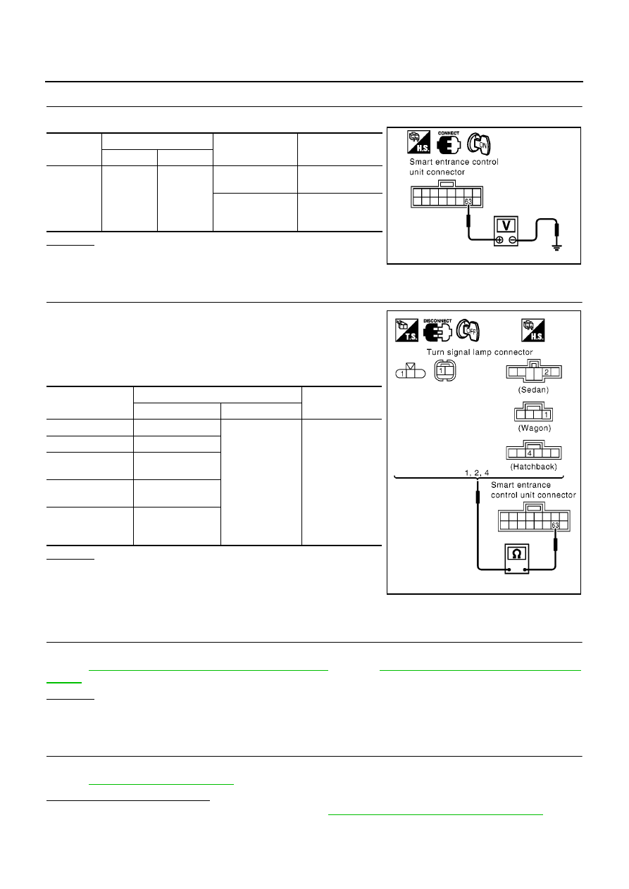
POWER SUPPLY CIRCUIT CHECK
Check voltage between smart entrance control unit harness connector M43 terminal 63 (G/Y) and ground.
OK or NG
OK
>> GO TO 4.
NG
>> Replace the smart entrance control unit.
4.
TURN SIGNAL LAMP RH CIRCUIT CHECK
1.
Turn ignition switch OFF.
2.
Disconnect each turn signal lamp RH connector.
3.
Check continuity between the following harness connector ter-
minal of the each turn signal lamp RH and smart entrance con-
trol unit harness connector M43 terminal 63.
OK or NG
OK
>> Check harness for open or short between smart
entrance control unit and each turn signal lamps RH.
NG
>> Repair or replace harness.
RH and LH Turn Indicators Do Not Operate
EKS009MX
1.
COMBINATION METER POWER AND GROUND CIRCUIT CHECK
Check combination meter power and ground circuit check.
Refer to
DI-20, "Power Supply and Ground Circuit Check"
(LHD) or
DI-43, "Power Supply and Ground Circuit
(RHD).
OK or NG
OK
>> GO TO 2.
NG
>> Replace combination meter.
2.
SELF-DIAGNOSIS FOR SMART ENTRANCE CONTROL UNIT
Perform smart entrance control unit self-diagnosis mode.
Refer to
.
Does the display of CAN appear?
YES
>> Check the CAN communication line. Refer to
BCS-23, "CAN Communication Line Check"
.
NO
>> Replace combination meter.
Connector
Terminal (wire color)
Condition
Voltage (V)
(Approx.)
( + )
( - )
M43
64 (G/B)
Ground
Turn signal RH illu-
minates.
0
Turn signal RH
does not illumi-
nate.
Battery voltage
MKIB0068E
Connector
Terminals (wire color)
Continuity
(+)
(–)
E1
1 (G/Y)
63 (G/Y)
Yes
E24
1 (G/Y)
B39
(Wagon models)
1 (G/Y)
B64
(Sedan models)
2 (G/Y)
B91
(Hatchback
models)
4 (G/Y)
MKIB0602E
TURN SIGNAL AND HAZARD WARNING LAMPS
LT-59
C
D
E
F
G
H
I
J
L
M
A
B
LT
Bulb Replacement
EKS009MY
FRONT TURN SIGNAL LAMP
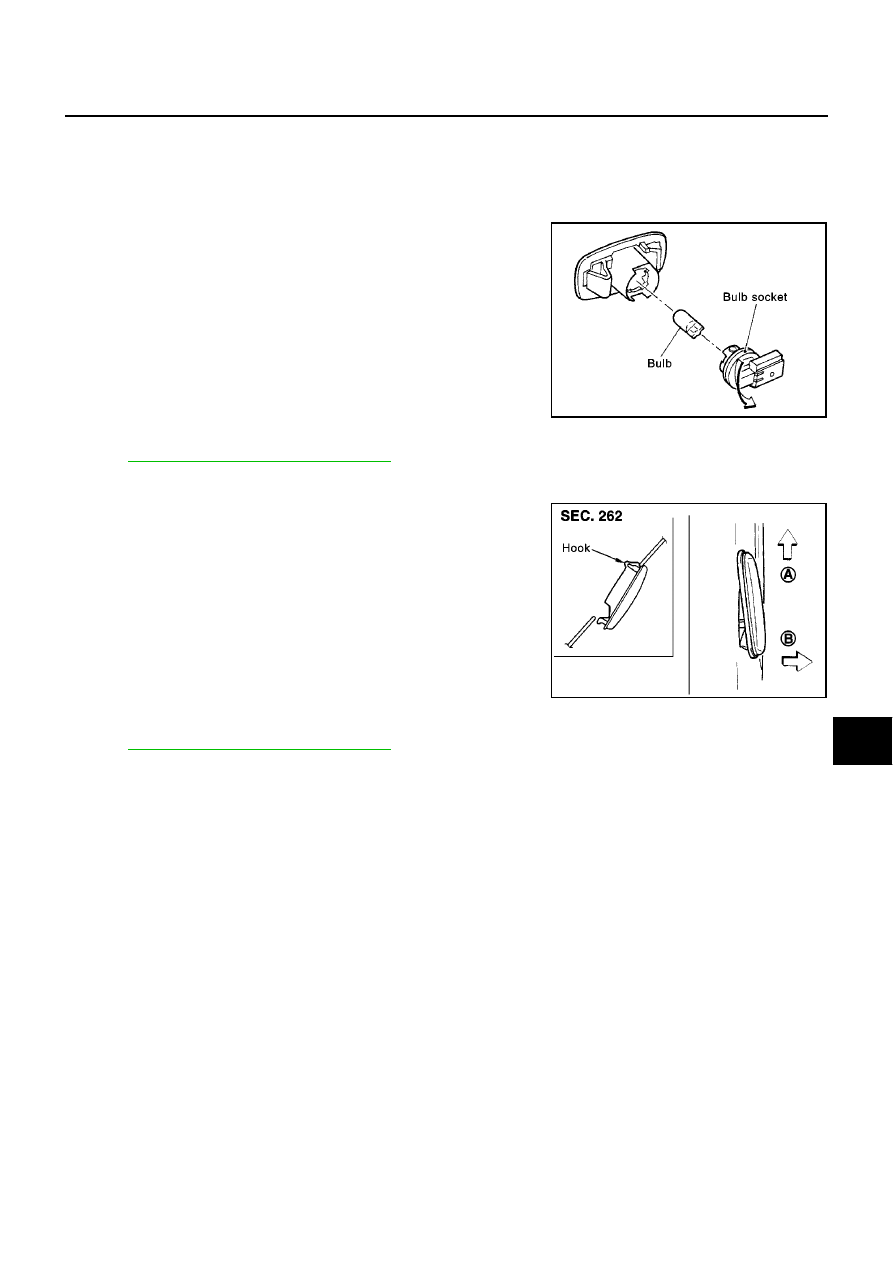
SIDE TURN SIGNAL LAMP
1.
Remove side turn signal lamp.
2.
Turn the bulb socket counterclockwise and unlock it.
3.
Remove the bulb from its socket.
REAR TURN SIGNAL LAMP
Refer to
LT-92, "REAR COMBINATION LAMP"
.
Removal and Installation for Side Turn Signal Lamp
EKS009MZ
1.
Push the side turn signal lamp toward A direction in the figure,
and pull up B direction in the figure.
2.
Disconnect the side turn signal lamp connector.
Removal and Installation for Rear Turn Signal Lamp
EKS009N0
Refer to
LT-92, "REAR COMBINATION LAMP"
.
Front turn signal lamp
: 12V - 21W (amber)
Side turn signal lamp
: 12V - 5W
PKIA0468E
PKIA0469E
LT-60
LIGHTING AND TURN SIGNAL SWITCH
LIGHTING AND TURN SIGNAL SWITCH
PFP:25540
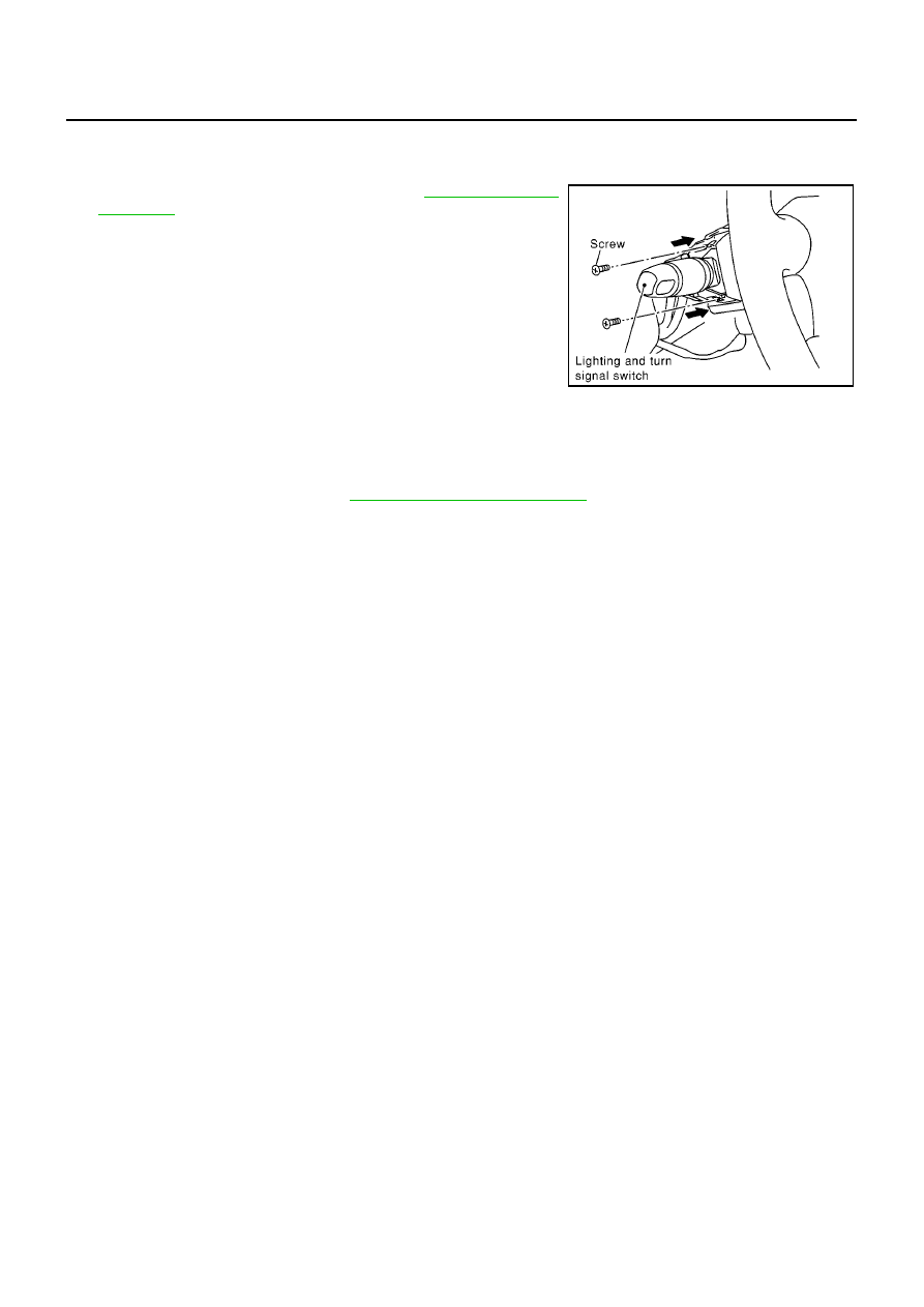
Removal and Installation
EKS009N1
1.
Remove the steering column cover. Refer to
.
2.
Remove lighting and turn signal switch mounting screw and
remove the lighting and turn signal switch from the spiral cable.
3.
Disconnect the lighting and turn signal switch connector.
Switch Circuit Inspection
EKS009N2
Using circuit tester, check continuity between the lighting and turn signal switch connector terminals in each
operation status of the switch. Refer to
LT-95, "Switch Circuit Inspection"
.
MKIA0054E
HAZARD SWITCH
LT-61
C
D
E
F
G
H
I
J
L
M
A
B
LT
HAZARD SWITCH
PFP:25290
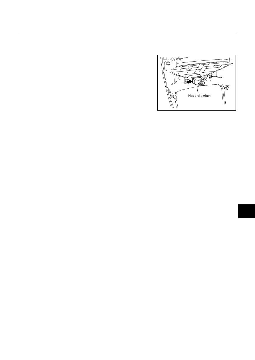
Removal and Installation
EKS009N3
REMOVAL
1.
Remove cluster lid C. Refer to IP section in P12 ESM (SM2E00-
1P12E0E) .
2.
Using a flat-bladed screwdriver or other suitable tool, press pawl
to remove hazard switch from cluster lid C.
INSTALLATION
Installation is in the reverse order of removal.
MKIB0120E
Нет комментариевНе стесняйтесь поделиться с нами вашим ценным мнением.
Текст