Nissan Primera P12. Manual — part 88
POWER DOOR LOCK — SUPER LOCK —
BL-61
C
D
E
F
G
H
J
K
L
M
A
B
BL
Door Lock/Unlock Switch Check
EIS005HF
1.
CHECK DOOR LOCK/UNLOCK SWITCH
WITH CONSULT-II
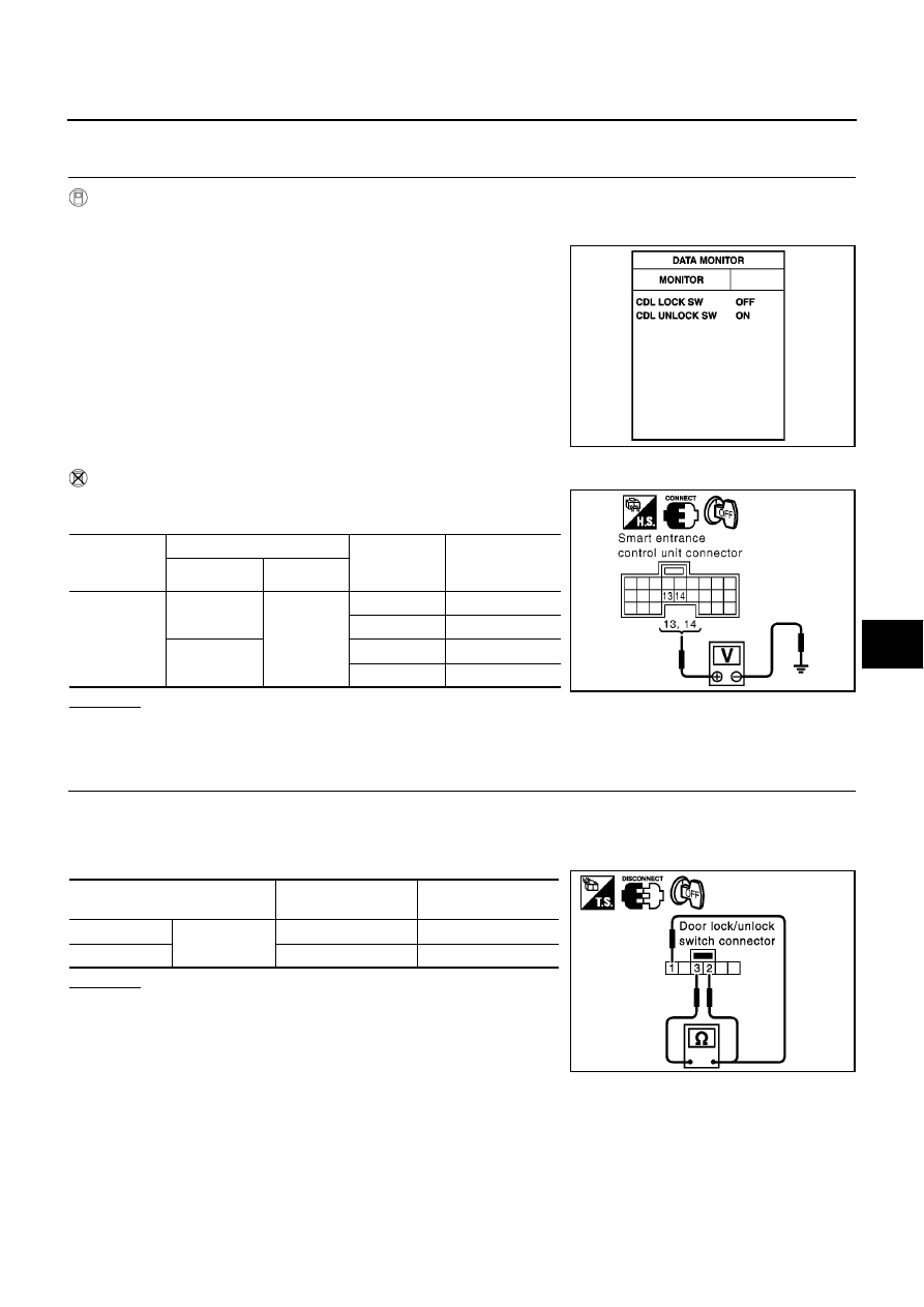
Check door lock/unlock switch signal (“CDL LOCK SW” or “CDL UNLOCK SW”) in “DATA MONITOR” mode
with CONSULT-II.
WITHOUT CONSULT-II
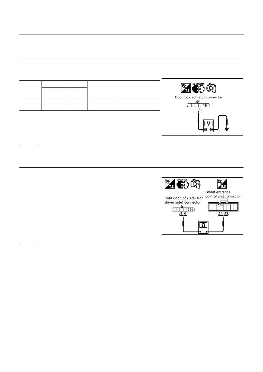
Check voltage between smart entrance control unit harness connec-
tor M41 terminals 13 or 14 and ground.
OK or NG
OK
>> Door lock/unlock switch is OK.
NG
>> GO TO 2.
2.
CHECK DOOR LOCK/UNLOCK SWITCH
1.
Turn ignition switch OFF.
2.
Disconnect door lock/unlock switch connector.
3.
Check continuity between door lock/unlock switch connector terminals 1, 2 and 3.
OK or NG
OK
>> Check the following.
●
Ground circuit for door lock/unlock switch
●
Harness for open short between door lock/unlock
switch and smart entrance control unit
NG
>> Replace door lock/unlock switch.
When door lock/unlock is
locked
: CDL LOCK SW ON
When door lock/unlock is
unlocked
: CDL UNLOCK SW ON
MKIB0198E
Connector
Terminals (wire color)
Condition
(Door lock/
unlock switch)
Voltage (V)
(Approx.)
(+)
(
−
)
M41
13 (GY)
Ground
Locked
0
Unlocked
Battery voltage
14 (BR/Y)
Locked
Battery voltage
Unlocked
0
MKIB0582E
Terminal
Door lock/unlock
switch condition
Continuity
1
3
Lock
Yes
2
Unlock
Yes
MKIB0261E
BL-62
POWER DOOR LOCK — SUPER LOCK —
Door Lock Actuator Check
EIS005HG
DRIVER SIDE
1.
CHECK DOOR LOCK SIGNAL
1.
Turn ignition switch OFF.
2.
Disconnect front door lock actuator (driver side) harness connector.
3.
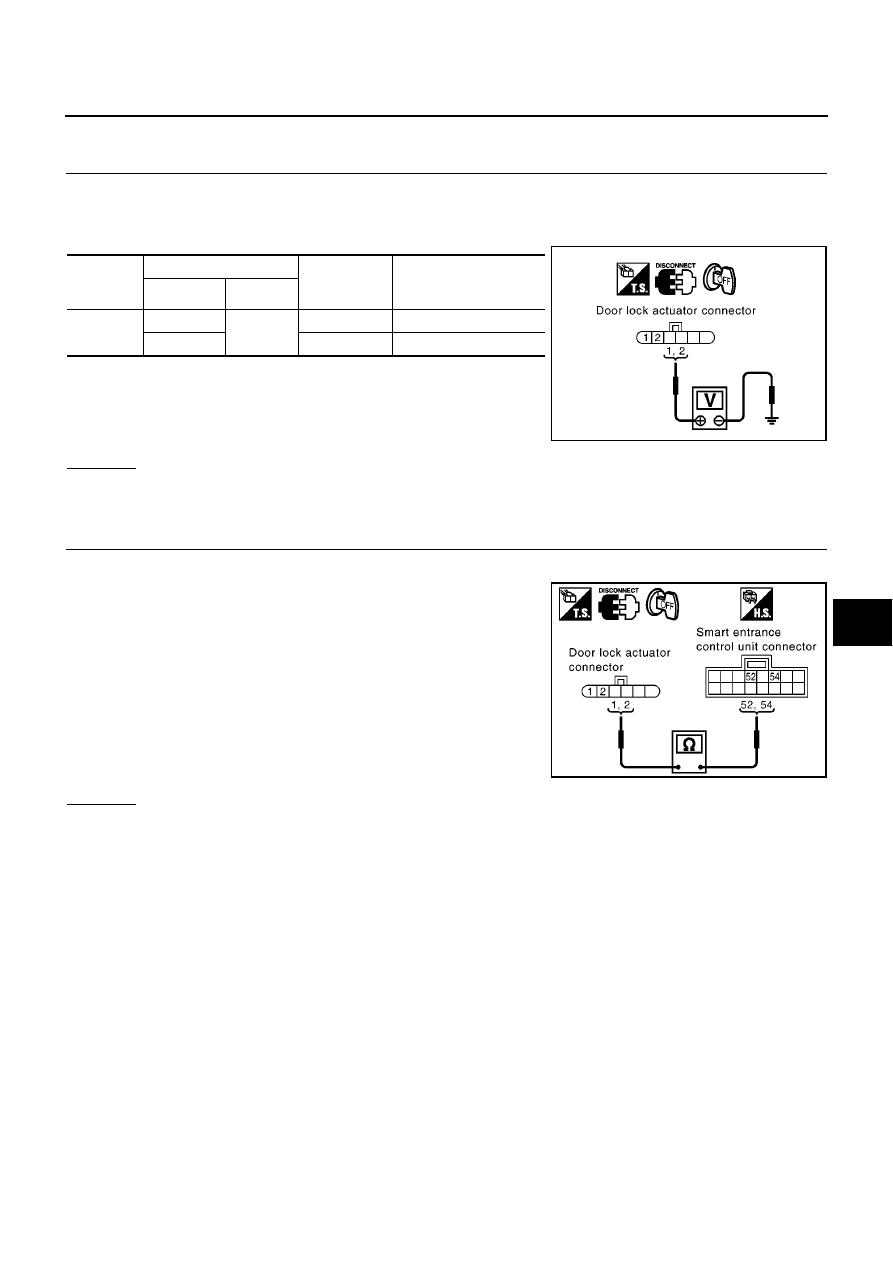
Check voltage between front door lock actuator harness connector and ground.
OK or NG
OK
>> Replace front door lock actuator (driver side).
NG
>> GO TO 2.
2.
CHECK DOOR LOCK ACTUATOR CIRCUIT
1.
Disconnect smart entrance control unit harness connector.
2.
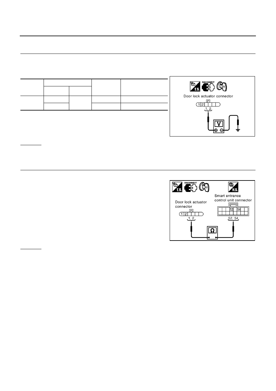
Check continuity between front door lock actuator (driver side)
harness connector D9 terminal 5, 6 and smart entrance control
unit harness connector M43 terminal 51, 52.
OK or NG
OK
>> Replace smart entrance control unit.
NG
>> Repair or replace harness between smart entrance control unit and front door lock actuator (driver
side).
Connector
Terminals (wire color)
Door lock/
unlock switch
condition
Voltage (V)
(Approx.)
(+)
(
−
)
D9
5 (Y)
Ground
Unlock
0
→
Battery voltage
→
0
6 (L/R)
Lock
0
→
Battery voltage
→
0
MIIB0463E
5 (Y) - 52 (Y)
: Continuity should exist.
6 (L/R) - 51 (L/R)
: Continuity should exist.
MIIB0464E
POWER DOOR LOCK — SUPER LOCK —
BL-63
C
D
E
F
G
H
J
K
L
M
A
B
BL
PASSENGER SIDE
1.
CHECK DOOR LOCK SIGNAL
1.
Turn ignition switch OFF.
2.
Disconnect front door lock actuator (passenger side) harness connector.
3.
Check voltage between front door lock actuator harness connector and ground.
OK or NG
OK
>> Replace front door lock actuator (passenger side).
NG
>> GO TO 2.
2.
CHECK DOOR LOCK ACTUATOR CIRCUIT
1.
Disconnect smart entrance control unit harness connector.
2.
Check continuity between front door lock actuator (passenger
side) harness connector D38 terminal 1, 2 and smart entrance
control unit harness connector M43 terminal 52, 54.
OK or NG
OK
>> Replace smart entrance control unit.
NG
>> Repairer replace harness between smart entrance control unit and front door lock actuator (pas-
senger side).
Connector
Terminals (wire color)
Door lock/
unlock switch
condition
Voltage (V)
(Approx.)
(+)
(
−
)
D38
1 (G/Y)
Ground
Unlock
0
→
Battery voltage
→
0
2 (Y)
Lock
0
→
Battery voltage
→
0
MIIB0465E
1 (G/Y) - 54 (G/Y)
: Continuity should exist.
2 (Y) - 52 (Y)
: Continuity should exist.
MIIB0466E
BL-64
POWER DOOR LOCK — SUPER LOCK —
REAR LH SIDE
1.
CHECK DOOR LOCK SIGNAL
1.
Turn ignition switch OFF.
2.
Disconnect rear door lock actuator LH harness connector.
3.
Check voltage between door lock actuator harness connector and ground.
OK or NG
OK
>> Replace rear door lock actuator LH.
NG
>> GO TO 2.
2.
CHECK DOOR LOCK ACTUATOR CIRCUIT
1.
Disconnect smart entrance control unit harness connector.
2.
Check continuity between rear door lock actuator LH harness
connector D56 terminal 1, 2 and smart entrance control unit har-
ness connector M43 terminal 52, 54.
OK or NG
OK
>> Replace smart entrance control unit.
NG
>> Repair or replace harness between smart entrance control unit and rear door lock actuator LH.
Connector
Terminals (wire color)
Door lock/
unlock switch
condition
Voltage (V)
(Approx.)
(+)
(
−
)
D56
1 (G/Y)
Ground
Unlock
0
→
Battery voltage
→
0
2 (Y)
Lock
0
→
Battery voltage
→
0
MIIB0465E
1 (G/Y) - 54 (G/Y)
: Continuity should exist.
2 (Y) - 52 (Y)
: Continuity should exist.
MIIB0466E
Нет комментариевНе стесняйтесь поделиться с нами вашим ценным мнением.
Текст