Nissan Primera P12. Manual — part 348
DTC P1272 FUEL PUMP
EC-577
[YD (WITHOUT EURO-OBD)]
C
D
E
F
G
H
I
J
K
L
M
A
EC
Diagnostic Procedure
EBS015AR
1.
PERFORM FUEL PUMP LEARNING VALUE CLEARING
NOTE:
If the DTC is detected because of air mixed with fuel (i.e.: caused by lack of fuel), it may become normal by
performing following procedure.
With CONSULT-II
1.
Turn ignition switch ON.
2.
Perform Fuel Pump Learning value clearing. Refer to
EC-368, "Fuel Pump Learning Value Clearing"
.
3.
Start engine and let it idle for at least 60 seconds.
4.
Select “SELF-DIAG RESULT” mode with CONSULT-II.
5.
Touch “ERASE”.
6.
Perform
EC-575, "DTC Confirmation Procedure"
, again.
7.
Is DTC detected again?
Yes or No
Yes
>> GO TO 2.
No
>> INSPECTION END
2.
CHECK FUEL PUMP POWER SUPPLY CIRCUIT FOR OPEN AND SHORT
1.
Turn ignition switch OFF.
2.
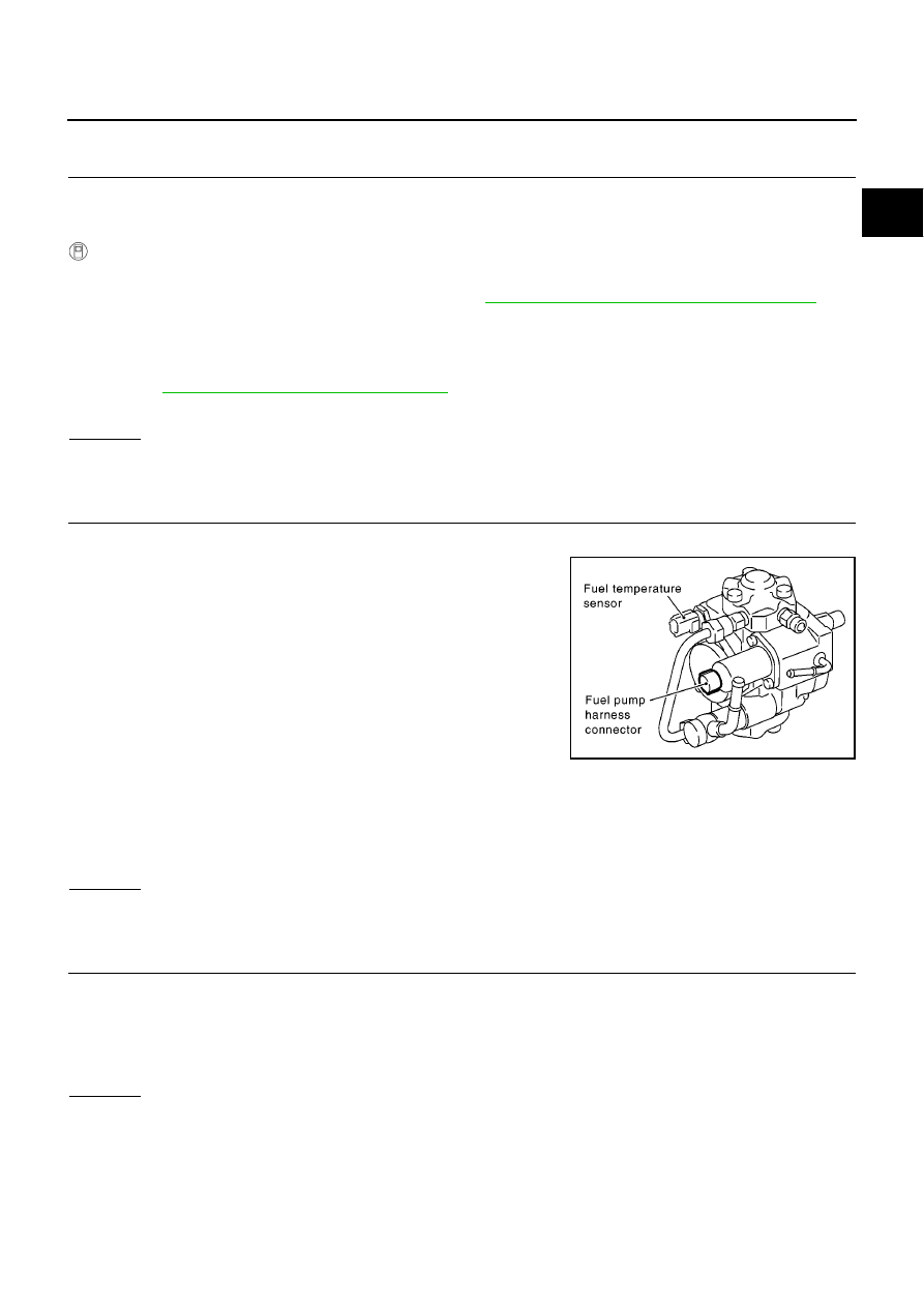
Disconnect ECM harness connector and fuel pump harness
connectors.
3.
Check harness continuity between ECM terminal 10 and fuel pump terminal 1.
Refer to Wiring Diagram.
4.
Also check harness for short to ground and short to power.
OK or NG
OK
>> GO TO 3.
NG
>> Repair open circuit or short to ground or short to power in harness or connectors.
3.
CHECK FUEL PUMP GROUND CIRCUIT FOR OPEN AND SHORT
1.
Check harness continuity between ECM terminal 29 and fuel pump terminal 2.
Refer to Wiring Diagram.
2.
Also check harness for short to ground and short to power.
OK or NG
OK
>> GO TO 4.
NG
>> Repair open circuit or short to ground or short to power in harness or connectors.
PBIB1943E
Continuity should exist.
Continuity should exist.
EC-578
[YD (WITHOUT EURO-OBD)]
DTC P1272 FUEL PUMP
4.
CHECK FUEL PUMP
Refer to
EC-578, "Component Inspection"
.
OK or NG
OK
>> GO TO 5.
NG
>> GO TO 7.
5.
CHECK FUEL RAIL PRESSURE SENSOR
Refer to
EC-456, "Component Inspection"
.
OK or NG
OK
>> GO TO 6.
NG
>> Replace fuel rail.
6.
CHECK INTERMITTENT INCIDENT
Refer to
EC-408, "TROUBLE DIAGNOSIS FOR INTERMITTENT INCIDENT"
.
OK or NG
OK
>> GO TO 7.
NG
>> Repair or replace.
7.
REPLACE FUEL PUMP
1.
Replace fuel pump.
2.
Perform Fuel Pump Learning Value Clearing. Refer to
EC-368, "Fuel Pump Learning Value Clearing"
.
>> INSPECTION END
Component Inspection
EBS015AS
FUEL PUMP
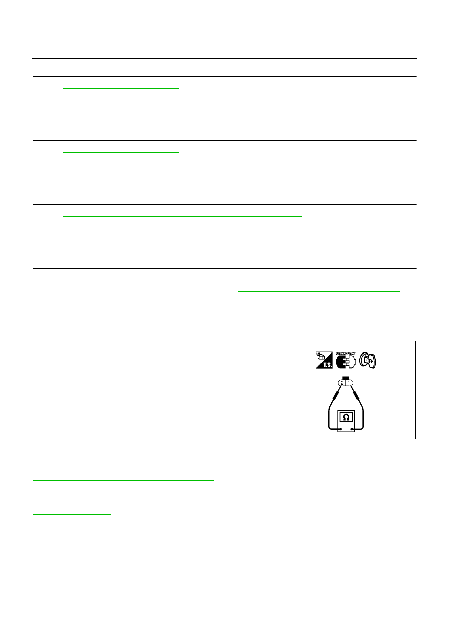
1.
Check continuity between fuel supply pump terminals 1 and 2.
2.
If NG, replace fuel pump.
Removal and Installation
EBS015AT
FUEL RAIL
Refer to
EM-39, "INJECTION TUBE AND FUEL INJECTOR"
FUEL PUMP
Refer to
Continuity should exist.
MBIB0623E
DTC P1273 FUEL PUMP
EC-579
[YD (WITHOUT EURO-OBD)]
C
D
E
F
G
H
I
J
K
L
M
A
EC
DTC P1273 FUEL PUMP
PFP:16700
Description
EBS015AU
To control the amount of the fuel inhalation of the fuel pump, a plunger is built into the fuel pump. When the
amount of the fuel inhalation of fuel pump increases, the fuel raises the fuel exhalation pressure. As a result,
the fuel injection pressure is raised. When the load of the engine increases, the ECM sends a signal to the fuel
pump to raise the injection pressure.
CONSULT-II Reference Value in Data Monitor Mode
EBS015AV
Specification data are reference values.
ECM Terminals and Reference Value
EBS015AW
Specification data are reference values and are measured between each terminal and ground.
Pulse signal is measured by CONSULT-II.
CAUTION:
Do not use ECM ground terminals when measuring input/output voltage. Doing so may result in dam-
age to the ECM's transistor. Use a ground other than ECM terminals, such as the ground.
MONITOR ITEM
CONDITION
SPECIFICATION
PUMP CURRENT
●
Engine: After warming up
●
Air conditioner switch: OFF
●
Shift lever: Neutral position
●
No-load
Idle
1,700 - 1,900 mA
2,000 rpm
1,600 - 1,800 mA
TERMI-
NAL
NO.
WIRE
COLOR
ITEM
CONDITION
DATA
(DC Voltage and Pulse Signal)
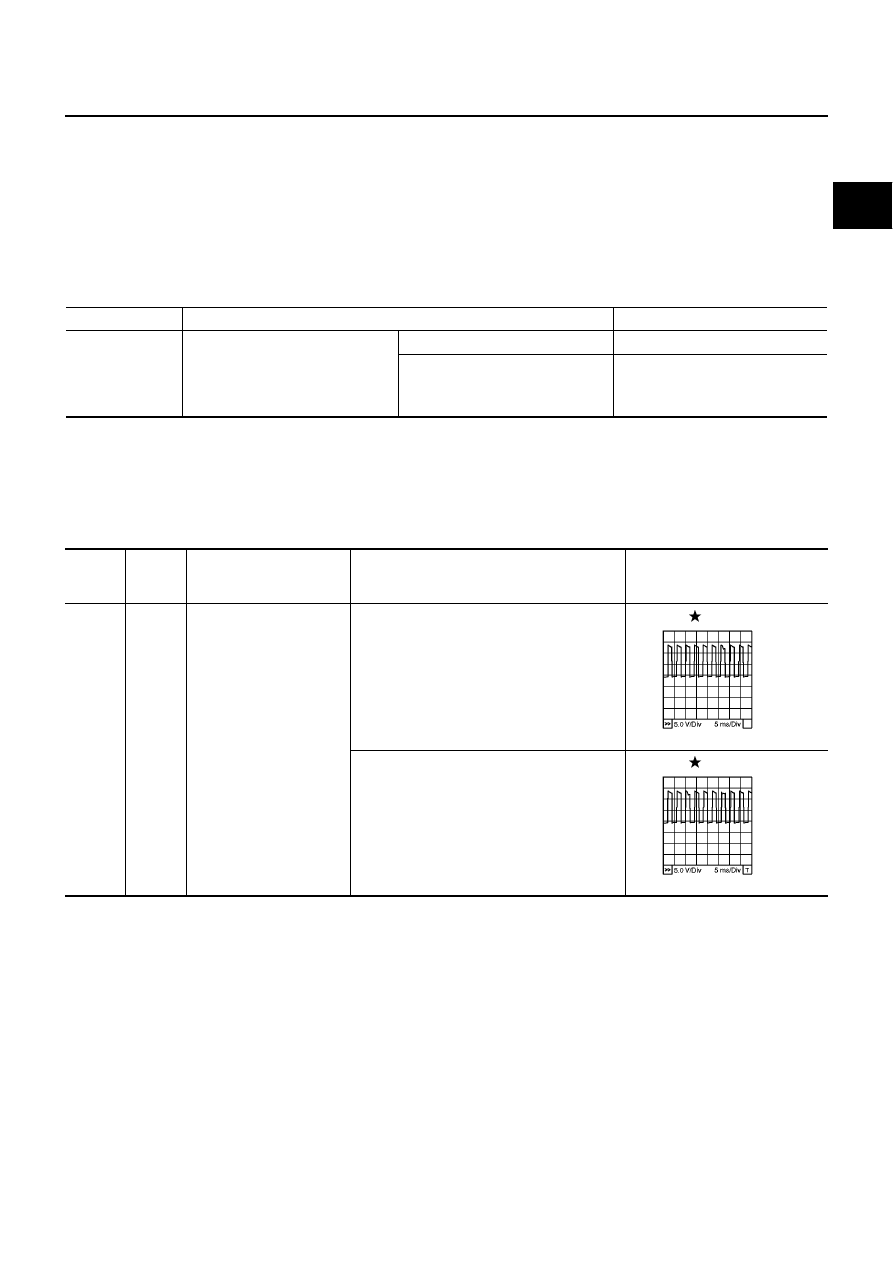
10
Y/L
Fuel pump power supply
[Engine is running]
●
Warm-up condition
●
Idle speed
0 - 12.5V
[Engine is running]
●
Warm-up condition
●
Engine speed is 2,000 rpm
0 - 12.5V
MBIB0885E
MBIB0886E
EC-580
[YD (WITHOUT EURO-OBD)]
DTC P1273 FUEL PUMP
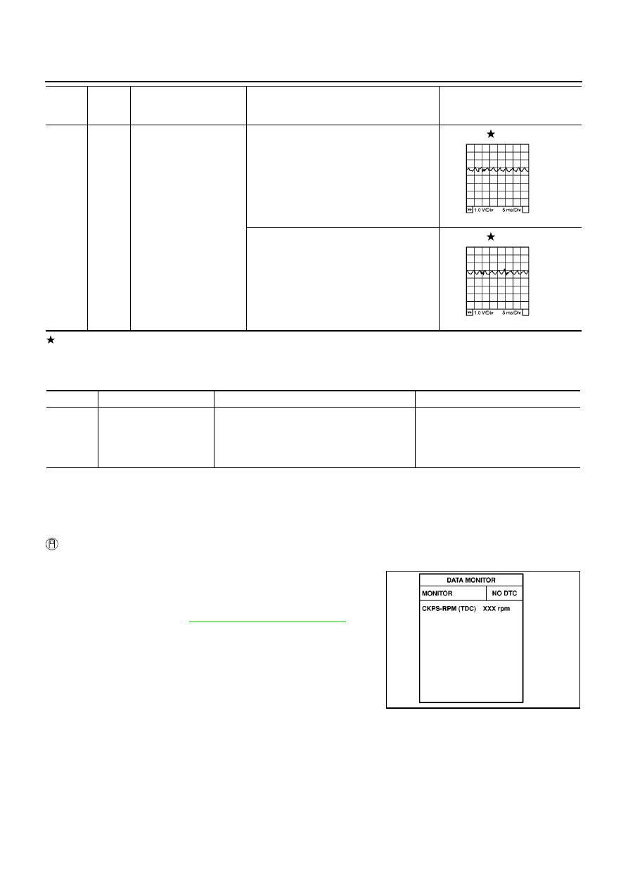
: Average voltage for pulse signal (Actual pulse signal can be confirmed by oscilloscope.)
On Board Diagnosis Logic
EBS015AX
The MI will not light up for these self-diagnoses.
DTC Confirmation Procedure
EBS015AY
NOTE:
If DTC Confirmation Procedure has been previously conducted, always turn ignition switch OFF and wait at
least 10 seconds before conducting the next test.
WITH CONSULT-II
1.
Start engine and warm it up to normal operating temperature.
2.
Select “DATA MONITOR” mode with CONSULT-II.
3.
Keep engine speed more than 2,000 rpm for at least 10 sec-
onds.
4.
If DTC is detected, go to
EC-582, "Diagnostic Procedure"
.
29
L
Fuel pump
[Engine is running]
●
Warm-up condition
●
Idle speed
0.5 - 1.0V
[Engine is running]
●
Warm-up condition
●
Engine speed is 2,000 rpm
0.5 - 1.0V
TERMI-
NAL
NO.
WIRE
COLOR
ITEM
CONDITION
DATA
(DC Voltage and Pulse Signal)
MBIB0887E
MBIB0888E
DTC No.
Trouble diagnosis name
DTC detecting condition
Possible cause
P1273
Fuel pump insufficient flow
ECM detects the abnormal pulse of fuel pres-
sure.
●
Fuel pump
●
Air mixed with fuel
●
Lack of fuel
●
Fuel rail pressure sensor
SEF817Y
Нет комментариевНе стесняйтесь поделиться с нами вашим ценным мнением.
Текст