Nissan Primera P12. Manual — part 442

EM-114
[YD]
CYLINDER BLOCK
Movement Amount in Rotation Direction
●
Check the movement amount in the following procedure.
1.
Install a bolt to clutch cover mounting hole, and place a torque wrench on the extended line of the flywheel
center line.
●
Tighten bolt at a force of 9.8 N·m (1kg-m, 87 in-lb) to keep it from loosening.
2.
Put a mating mark on circumferences of the two flywheel
masses without applying any load (Measurement standard
points).
3.
Apply a force of 9.8 N·m (1kg-m, 87 in-lb) in each direction, and
mark the movement amount on the mass on the transmission
side.
4.
Measure dimensions of movement amounts A and B on circum-
ference of the flywheel on the transmission side.
●
When measured value is outside the standard, replace flywheel.
Standard
: 26.2 mm (1.031 in) or less
KBIA0297E
SERVICE DATA AND SPECIFICATIONS (SDS)
EM-115
[YD]
C
D
E
F
G
H
I
J
K
L
M
A
EM
SERVICE DATA AND SPECIFICATIONS (SDS)
PFP:00030
Standard and Limit
EBS00SO7
GENERAL SPECIFICATIONS
INTAKE MANIFOLD AND EXHAUST MANIFOLD
Unit: mm (in)
DRIVE BELTS
Belt Deflection:
Unit: mm (in)
*: When engine is cold.
Cylinder arrangement
In-line 4
Displacement
Unit: cm
3
(cu in)
2,184 (133.27)
Bore and stroke
Unit: mm (in)
86 x 94 (3.39 x 3.70)
Valve arrangement
DOHC
Firing order
1-3-4-2
Number of piston rings
Compression
2
Oil
1
Number of main bearings
5
Compression ratio
16.7
Compression pressure
Unit: kPa (bar, kg/cm
2
, psi)/200 rpm
Standard
2,991 (29.9, 30.5, 434)
Minimum
2,452 (24.5, 25.0, 356)
Differential limit between cylinders
490 (4.9, 5.0, 71)
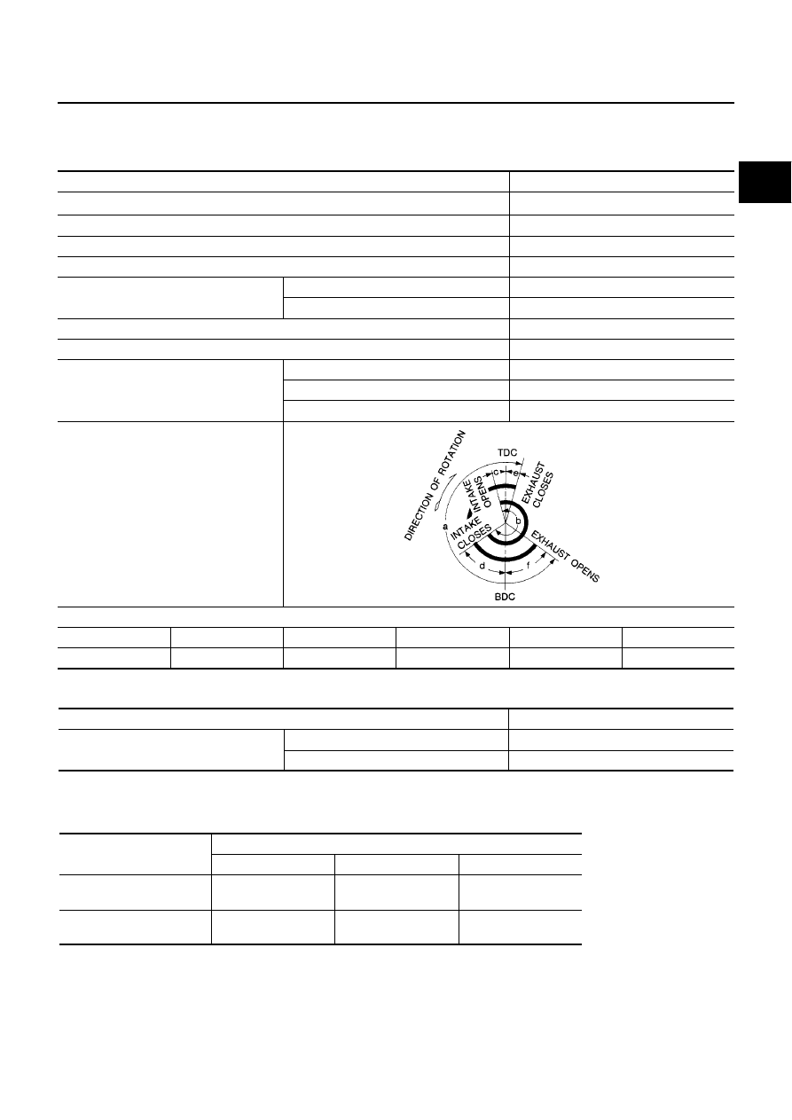
Valve timing
Unit: degree
a
b
c
d
e
f
224
212
2
30
-2
46
EM120
Item
Limit
Surface distortion
Intake manifold
0.1 (0.004)
Exhaust manifold
0.3 (0.012)
Applied belt
Belt deflection with 98 N (10 kg, 22 lb) force applied*
New
Adjusted
Limit for re-adjusting
Air conditioner compressor
belt
4 - 5
(0.16 - 0.20)
6 - 7
(0.24 - 0.28)
8.5 (0.335)
Alternator & water pump
belt
9.0 - 10.5
(0.354 - 0.413)
11.0 - 12.5
(0.433 - 0.492)
16.5 (0.650)
EM-116
[YD]
SERVICE DATA AND SPECIFICATIONS (SDS)
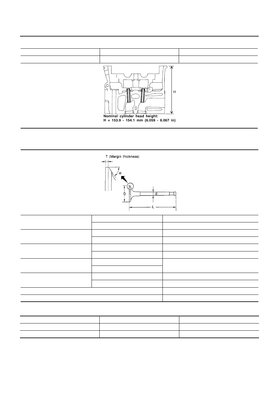
CYLINDER HEAD
Unit: mm (in)
VALVE
Valve
Unit: mm (in)
Valve Clearance
Unit: mm (in)
*1: Approximately 20
°
C (68
°
F)
*2: Approximately 80
°
C (176
°
F)
Item
Standard
Limit
Head surface distortion
Less than 0.03 (0.0012)
0.04 (0.0016)
JEM204G
Valve head diameter “D”
Intake
28.0 - 28.3 (1.102 - 1.114)
Exhaust
26.0 - 26.3 (1.024 - 1.035)
Valve length “L”
Intake
106.72 (4.2016)
Exhaust
106.36 (4.1874)
Valve stem diameter “d”
Intake
5.965 - 5.980 (0.2348 - 0.2354)
Exhaust
5.945 - 5.960 (0.2341 - 0.2346)
Valve seat angle “
α
”
Intake
45
°
15
′
- 45
°
45
′
Exhaust
Valve margin “T”
Intake
1.38 (0.0543)
Exhaust
1.48 (0.0583)
Valve margin “T” limit
More than 1.0 (0.039)
Valve stem end surface grinding limit
Less than 0.2 (0.008)
SEM188
Item
Cold*1
Hot*2 (reference data)
Intake
0.24 - 0.32 (0.0094 - 0.0126)
0.274 - 0.386 (0.011 - 0.015)
Exhaust
0.26 - 0.34 (0.0102 - 0.0134)
0.308 - 0.432 (0.012 - 0.017)
SERVICE DATA AND SPECIFICATIONS (SDS)
EM-117
[YD]
C
D
E
F
G
H
I
J
K
L
M
A
EM
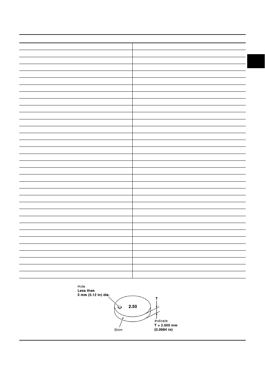
Available Shims
Stamped mark
Thickness
mm (in)
2.10
2.10 (0.0827)
2.12
2.12 (0.0835)
2.14
2.14 (0.0843)
2.16
2.16 (0.0850)
2.18
2.18 (0.0858)
2.20
2.20 (0.0866)
2.22
2.22 (0.0874)
2.24
2.24 (0.0882)
2.26
2.26 (0.0890)
2.28
2.28 (0.0898)
2.30
2.30 (0.0906)
2.32
2.32 (0.0913)
2.34
2.34 (0.0921)
2.36
2.36 (0.0929)
2.38
2.38 (0.0937)
2.40
2.40 (0.0954)
2.42
2.42 (0.0953)
2.44
2.44 (0.0961)
2.46
2.46 (0.0969)
2.48
2.48 (0.0976)
2.50
2.50 (0.0984)
2.52
2.52 (0.0992)
2.54
2.54 (0.1000)
2.56
2.56 (0.1008)
2.58
2.58 (0.1016)
2.60
2.60 (0.1024)
2.62
2.62 (0.1031)
2.64
2.64 (0.1039)
2.66
2.66 (0.1047)
2.68
2.68 (0.1055)
2.70
2.70 (0.1063)
2.72
2.72 (0.1071)
2.74
2.74 (0.1079)
SEM512G
Нет комментариевНе стесняйтесь поделиться с нами вашим ценным мнением.
Текст