Nissan Primera P12. Manual — part 92
POWER DOOR LOCK — SUPER LOCK —
BL-77
C
D
E
F
G
H
J
K
L
M
A
B
BL
3.
CHECK SMART ENTRANCE CONTROL UNIT OUTPUT SIGNAL
1.
Connect trunk release actuator and smart entrance control unit connector.
2.
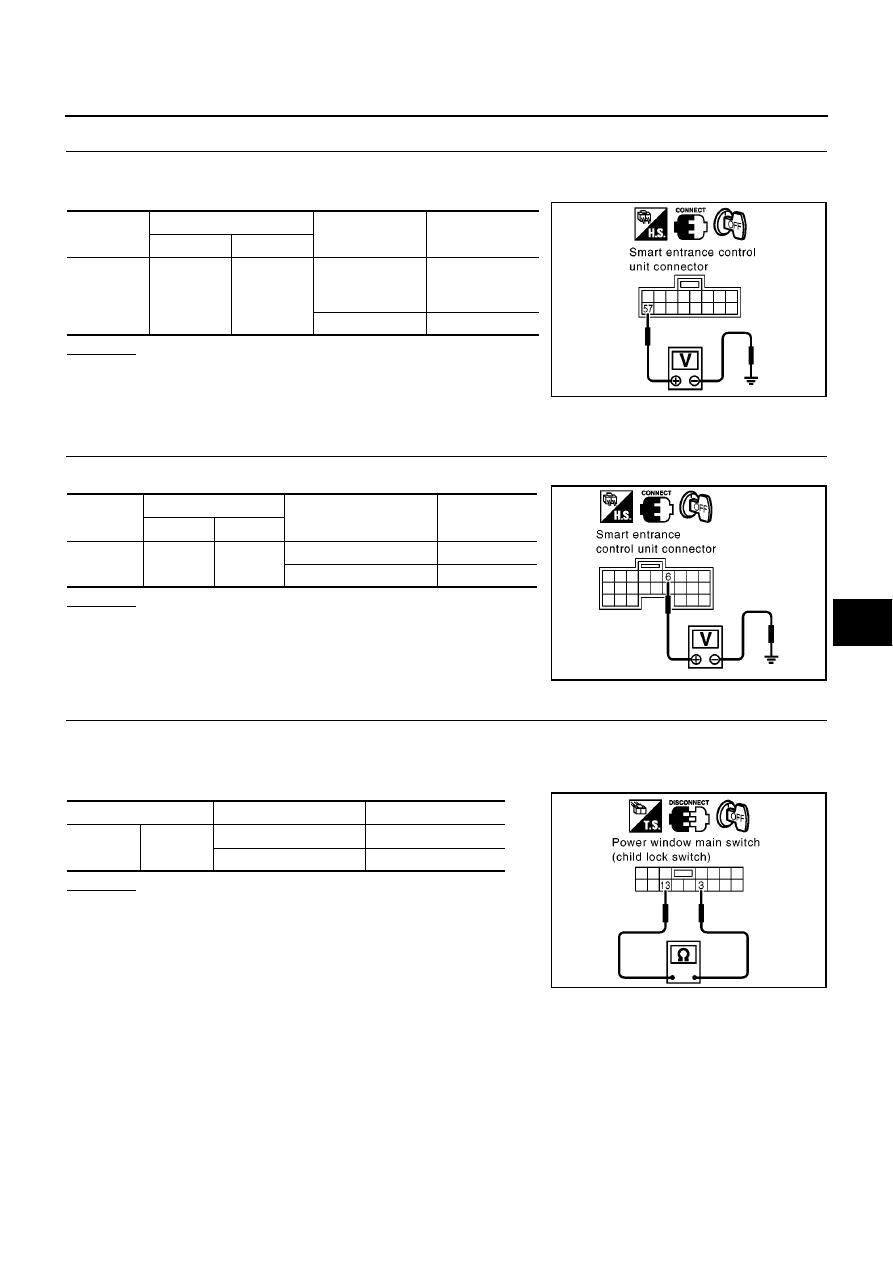
Check voltage between smart entrance control unit connector and ground.
OK or NG
OK
>> Replace back door release actuator.
NG
>> Replace smart entrance control unit.
Child Lock Switch Check
EIS0061O
1.
CHECK CHILD LOCK SWITCH INPUT SIGNAL
Check voltage between smart entrance control unit harness connector and ground.
OK or NG
OK
>> Child lock switch is OK.
NG
>> GO TO 2.
2.
CHECK CHILD LOCK SWITCH
1.
Turn ignition switch OFF.
2.
Disconnect power window main switch connector.
3.
Check continuity between power window main switch terminals 3 and 13.
OK or NG
OK
>> Check the following.
●
Harness for open or short between power window
main switch and smart entrance control unit
●
Power window main switch ground circuit
NG
>> Replace power window main switch.
Connector
Terminal (wire color)
Condition
Voltage (V)
(Approx.)
(+)
(–)
M43
57 (G/B)
Ground
Back door
release switch:
ON
0
Other than above
Battery voltage
MIIB0474E
Connector
Terminals (wire color)
Child lock switch
Voltage (V)
(Approx.)
(+)
(–)
M41
6 (BR)
Ground
Unlock operation
0
Lock operation
5
SIIA1614E
Terminals
Child lock switch
Continuity
3
13
Unlock operation
Yes
Lock operation
No
SIIA1615E
BL-78
POWER DOOR LOCK — SUPER LOCK —
Super Lock State Switch Check
EIS0061P
1.
CHECK SUPER LOCK STATE SWITCH INPUT SIGNAL
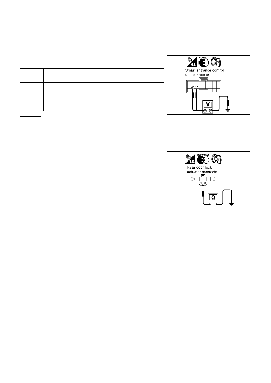
Check voltage between smart entrance control unit harness connec-
tor and ground.
OK or NG
OK
>> Super lock status switch is OK.
NG
>> GO TO 2
2.
CHECK REAR DOOR LOCK ACTUATOR GROUND CIRCUIT
1.
Turn ignition switch OFF.
2.
Disconnect rear door lock actuator connector.
3.
Check continuity between rear door lock actuator terminals 6
(LH) or 1 (RH) and ground.
OK or NG
OK
>> Harness for open or short between rear door lock actua-
tor and smart entrance control unit
NG
>> Repair or replace harness.
Connector
Terminals (wire color)
Rear door lock actuator
condition
Voltage (V)
(Approx.)
(+)
(–)
M42
35 (Y/B)
Ground
Super locked
0
Not super locked
5
36 (R/W)
Super locked
0
Not super locked
5
SIIA1633E
6 (B) - Ground
: Continuity should exist.
1 (B) - Ground
: Continuity should exist.
MIIB0472E
MULTI-REMOTE CONTROL SYSTEM
BL-79
C
D
E
F
G
H
J
K
L
M
A
B
BL
MULTI-REMOTE CONTROL SYSTEM
PFP:28596
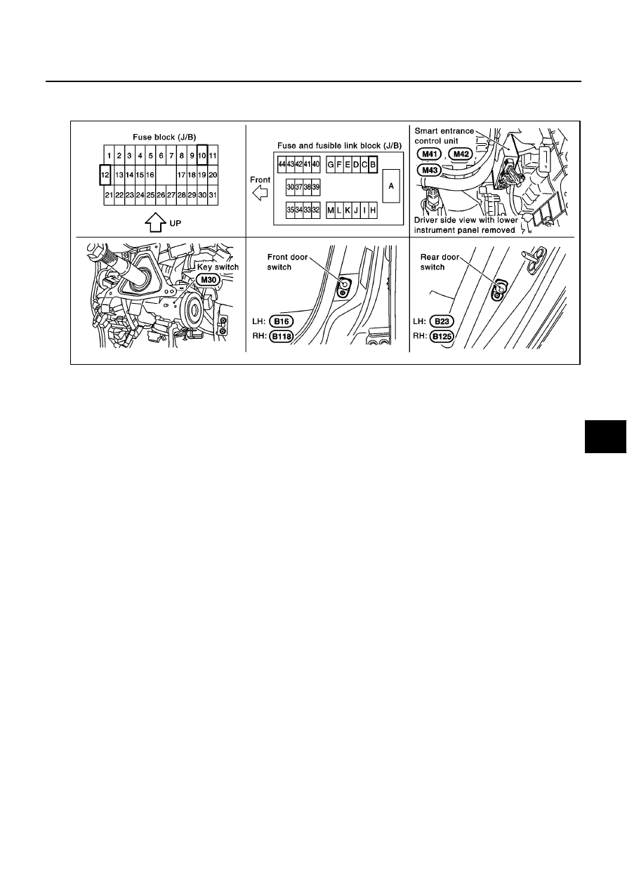
Component Parts and Harness Connector Location
EIS005HQ
SIIA1639E
BL-80
MULTI-REMOTE CONTROL SYSTEM
System Description
EIS005HR
INPUTS
Power is supplied at all times
●
through 10A fuse (No.12, located in the fusible link and fuse box)
●
to smart entrance control unit terminal 56 and
●
to key switch terminal 1.
●
through 40A fusible link (letter B, located in the fusible link and fuse box)
●
to smart entrance control unit terminal 49.
When the key switch is ON (Ignition key is inserted in key cylinder), power is supplied
●
through key switch terminal 2
●
to smart entrance control unit terminal 5.
When the front door switch (driver side) is ON (door is open), ground supplied
●
to smart entrance control unit terminal 43
●
through front door switch (driver side) terminal 1
●
through front door switch (drive side) case ground.
When the front door switch (passenger side) is ON (door is open), ground supplied
●
to smart entrance control unit terminal 44
●
through front door switch (passenger side) terminal 1
●
through front door switch (passenger side) case ground.
When the rear door switch (LH) are ON (door is open), ground is supplied
●
to smart entrance control unit terminal 45(LHD models) or 39(RHD models)
●
through rear door switch (LH) terminal 1
●
through rear door switch (LH) case ground.
When the rear door switch (RH) are ON (door is open), ground is supplied
●
to smart entrance control unit terminal 39(LHD models) or 45(RHD models)
●
through rear door switch (RH) terminal 1
●
through rear door switch (RH) case ground.
Remote controller signal is inputted to smart entrance control unit (The antenna of the system is combined
with smart entrance control unit).
The multi-remote control system controls operation of the
●
power door lock
●
hazard reminder
OPERATED PROCEDURE
Power Door Lock Operation
Models with super lock
Smart entrance control unit receives a LOCK signal from remote controller. Smart entrance control unit locks
all doors with input of LOCK signal from remote controller.
When an UNLOCK signal is sent from remote controller once, driver's door will be unlocked.
Then, if an UNLOCK signal is sent from remote controller again within 5 seconds, all door will be unlocked.
Models without super lock
Smart entrance control unit receives a LOCK/UNLOCK signal from remote controller. Smart entrance control
unit locks/unlocks all doors with input of LOCK/UNLOCK signal from remote controller.
Hazard Reminder
When the doors are locked or unlocked by remote controller, supply power to hazard warning lamp flashes as
follows
●
LOCK operation: Flash once
●
UNLOCK operation: Flash twice
Remote Controller ID Code Entry
A maximum of four remote controllers can be entered.
To enter ID code entry, the following signals must be input to the smart entrance control unit.
Нет комментариевНе стесняйтесь поделиться с нами вашим ценным мнением.
Текст