Nissan Primera P12. Manual — part 36
REFRIGERANT LINES
ATC-137
C
D
E
F
G
H
I
K
L
M
A
B
ATC
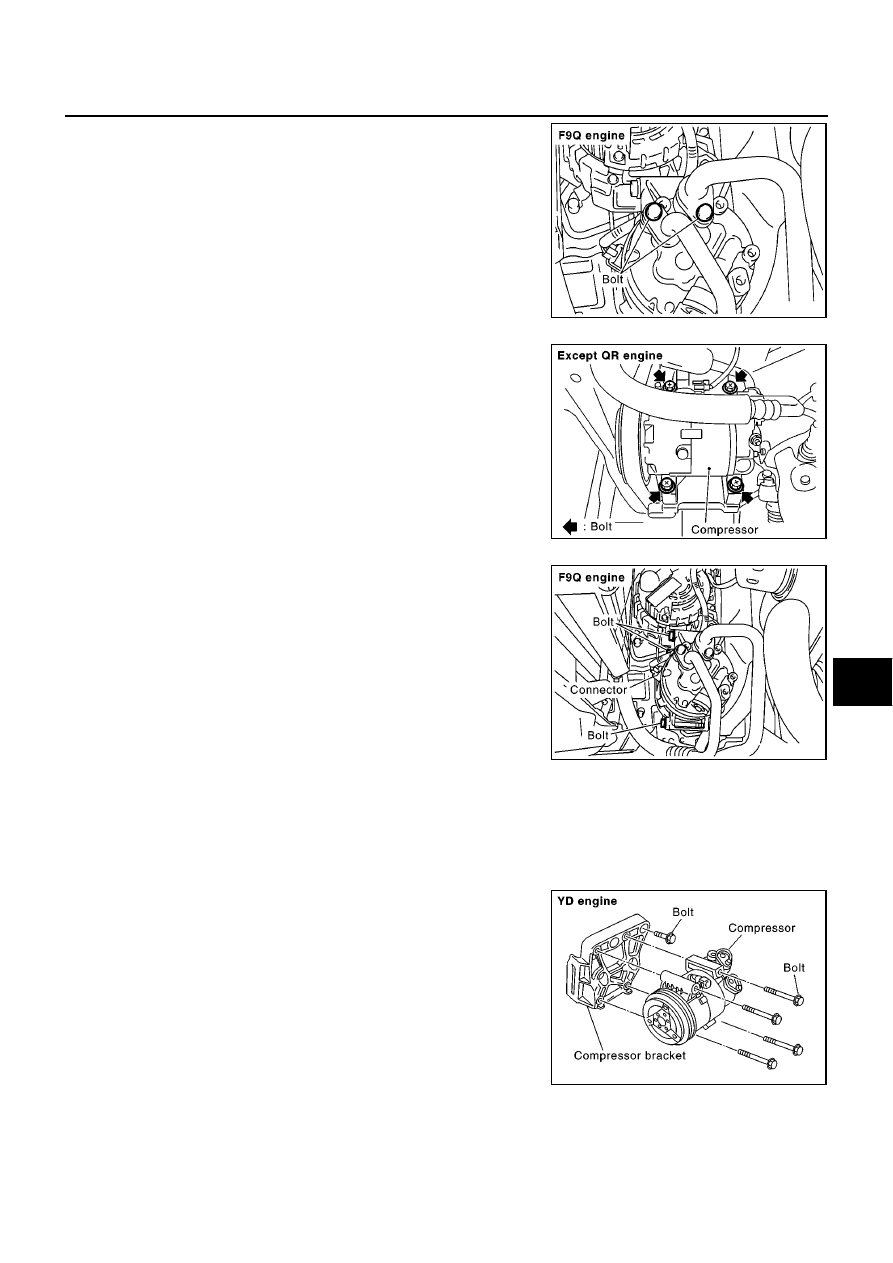
6.
Remove the mounting bolts from compressor.
7.
Remove the compressor from the lower side of the vehicle.
INSTALLATION
CAUTION:
●
Replace the O-ring of the low-pressure flexible hose and high-pressure flexible hose with a new
one, then apply compressor oil to it when installing it.
●
When pouring refrigerant, check for leaks.
RJIA2373E
RJIA0818E
RJIA2374E
Compressor mounting bolt (YD engine)
Tightening torque:
60 - 69 N·m (6.1 - 7.1 kg-m, 45 - 51
ft-lb)
Compressor bracket mounting bolt (YD engine)
Tightening torque:
57 - 65 N·m (5.8 - 6.7 kg-m, 42 - 48
ft-lb)
RJIA0838E
ATC-138
REFRIGERANT LINES
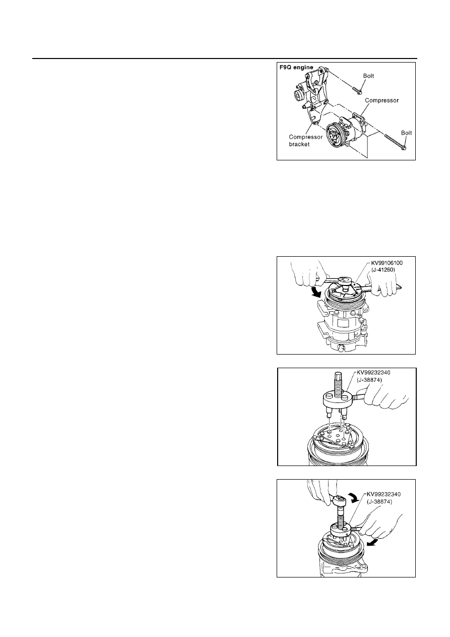
Compressor Clutch (Except F9Q Engine Models)
EJS003AB
REMOVAL
Overhaul
1.
When removing center bolt, hold clutch disc with wrench.
2.
Remove the clutch disc using the clutch disc puller.
Compressor mounting bolt (F9Q engine)
Tightening torque:
40 N·m (4.1 kg-m, 30 ft-lb)
Compressor bracket mounting bolt (F9Q engine)
Tightening torque:
21 N·m (2.1 kg-m, 15 ft-lb)
RJIA2375E
High-pressure flexible hose mounting bolt (nut)
Tightening torque:
7.8 - 19.6 N·m (0.8 - 2.0 kg-m, 69 - 173 in-lb)
Low-pressure flexible hose mounting bolt (nut)
Tightening torque:
7.8 - 19.6 N·m (0.8 - 2.0 kg-m, 69 - 173 in-lb)
RHA136EB
RHA399F
RHA124F
REFRIGERANT LINES
ATC-139
C
D
E
F
G
H
I
K
L
M
A
B
ATC
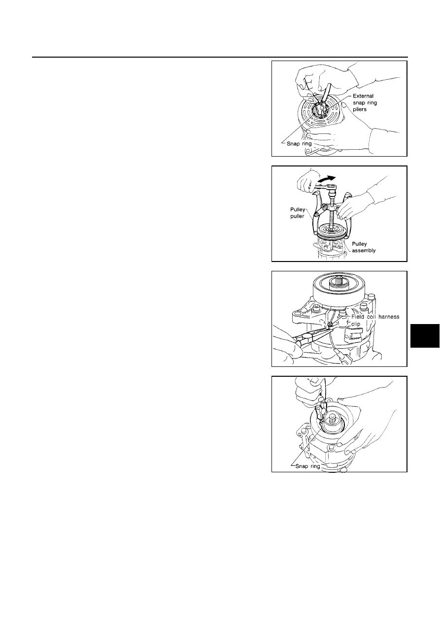
3.
Remove the snap ring using external snap ring pliers.
4.
Position the center pulley puller on the end of the drive shaft,
and remove the pulley assembly using any commercially avail-
able pulley puller.
To prevent the pulley groove from being deformed, the puller
claws should be positioned into the edge of the pulley assembly.
5.
Remove the field coil harness clip using a pair of pliers.
6.
Remove the snap ring using external snap ring pliers.
RHA138E
RHA139E
RHA125F
RHA145E
ATC-140
REFRIGERANT LINES
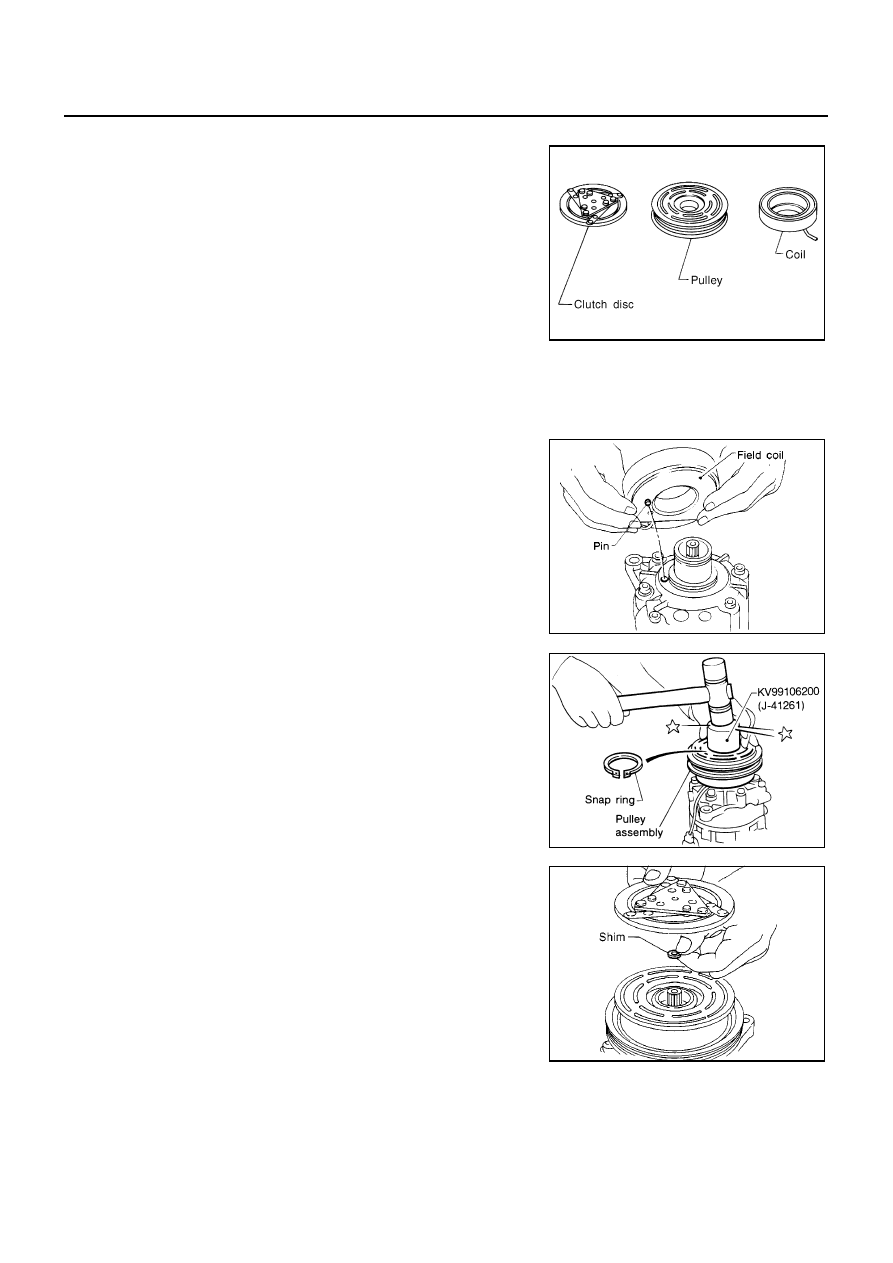
Inspection
Clutch disc
If the contact surface shows signs of damage due to excessive heat,
replace clutch disc and pulley.
Pulley
Check the appearance of the pulley assembly. If the contact surface
of pulley sows signs of excessive grooving, replace clutch disc and
pulley. The contact surfaces of the pulley assembly should be
cleaned with a suitable solvent before reinstallation.
Coil
Check coil for loose connection or cracked insulation.
INSTALLATION
1.
Install the field coil.
Be sure to align the coil
′
s pin with the hole in the compressor
′
s
front head.
2.
Install the field coil harness clip using a screwdriver.
3.
Install the pulley assembly using the installer and a hand press,
and then install the snap ring using snap ring pliers.
4.
Install the clutch disc on the drive shaft, together with the original
shim(s). Press the clutch disc down by hand.
RHA126F
RHA142E
RHA143EA
RHA127F
Нет комментариевНе стесняйтесь поделиться с нами вашим ценным мнением.
Текст