Nissan Primera P12. Manual — part 556
LAN-136
[CAN]
CAN SYSTEM (TYPE 28)
5.
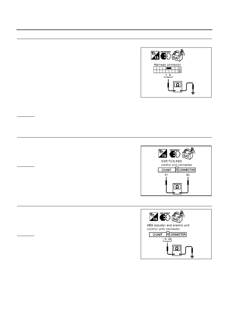
CHECK HARNESS FOR SHORT CIRCUIT
1.
Check the following.
●
Continuity between harness connector B102 terminals 1 (L),
8(G) and ground (Sedan models)
●
Continuity between harness connector B102 terminals 1 (L),
8(R) and ground (Hatch back and wagon models)
OK or NG
OK
>> GO TO 6.
NG
>> Repair harness between harness connector B102 and harness connector B107.
6.
CHECK HARNESS FOR SHORT CIRCUIT
1.
Disconnect ABS actuator and electric unit (control unit) connector.
2.
Check continuity between ABS actuator and electric unit (control
unit) harness connector E64 terminals 26 (L) and 15 (R).
OK or NG
OK
>> GO TO 7.
NG
>> Repair harness between ABS actuator and electric unit
(control unit) and harness connector E120.
7.
CHECK HARNESS FOR SHORT CIRCUIT
Check continuity between ABS actuator and electric unit (control
unit) harness connector E64 terminals 26 (L), 15 (R) and ground.
OK or NG
OK
>> GO TO 8.
NG
>> Repair harness between ABS actuator and electric unit
(control unit) and harness connector E120.
1 (L) – ground (Sedan
models)
: Continuity should not exist.
8 (G) – ground (Sedan
models)
: Continuity should not exist.
1 (L) – ground (Hatch
back and wagon models)
: Continuity should not exist.
8 (R) – ground (Hatch
back and wagon models)
: Continuity should not exist.
PKIA0833E
26 (L) – 15 (R)
: Continuity should not exist.
PKIA0818E
26 (L) – ground
: Continuity should not exist.
15 (R) – ground
: Continuity should not exist.
PKIA0834E
CAN SYSTEM (TYPE 28)
LAN-137
[CAN]
C
D
E
F
G
H
I
J
L
M
A
B
LAN
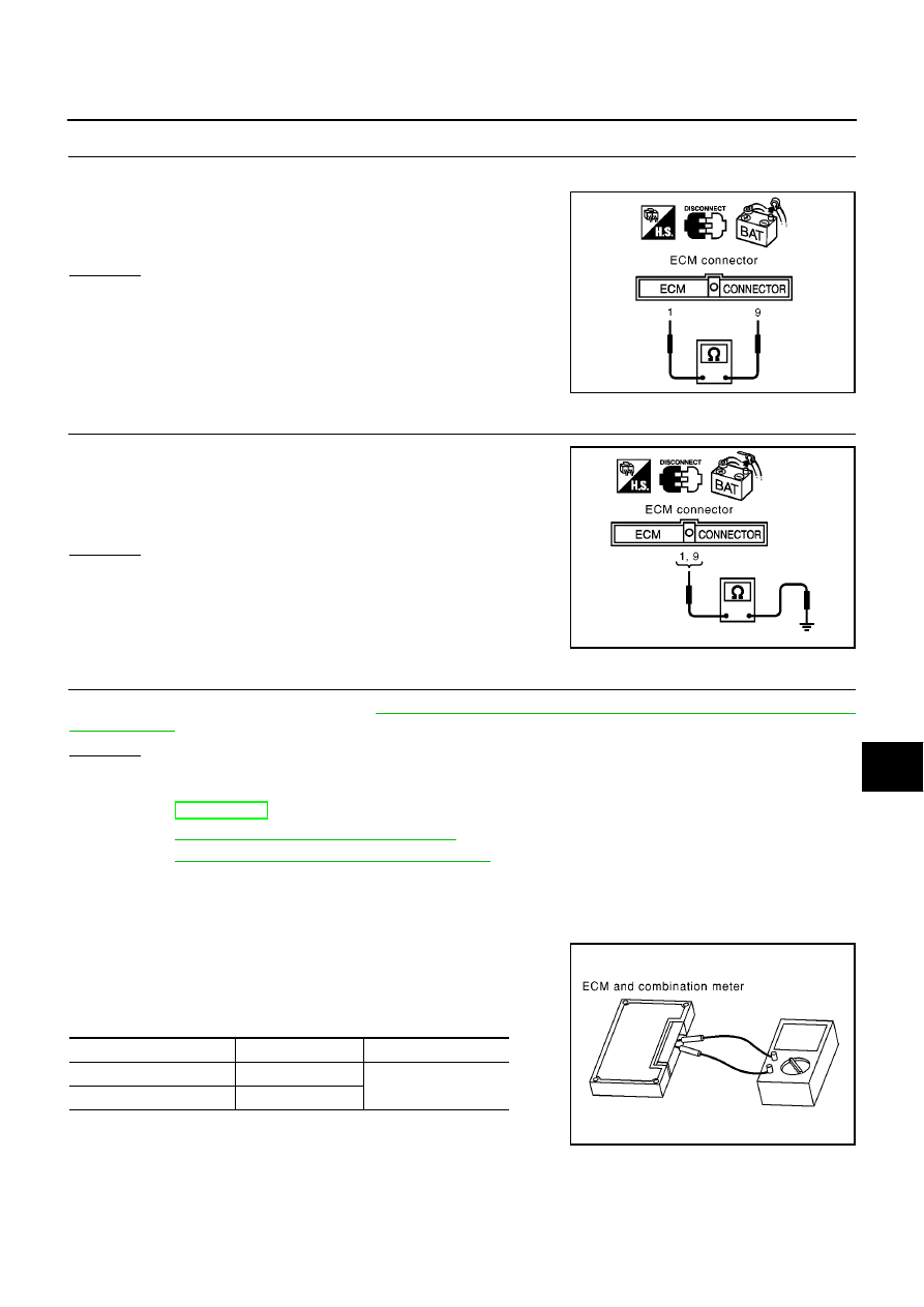
8.
CHECK HARNESS FOR SHORT CIRCUIT
1.
Disconnect ECM connector.
2.
Check continuity between ECM harness connector E81 termi-
nals 1 (L) and 9 (R).
OK or NG
OK
>> GO TO 9.
NG
>> Repair harness between ECM and harness connector
E125.
9.
CHECK HARNESS FOR SHORT CIRCUIT
Check continuity between ECM harness connector E81 terminals 1
(L), 9 (R) and ground.
OK or NG
OK
>> GO TO 10.
NG
>> Repair harness between ECM and harness connector
E125.
10.
ECM / COMBINATION METER INTERNAL CIRCUIT INSPECTION
Check components inspection. Refer to
LAN-137, "ECM / COMBINATION METER INTERNAL CIRCUIT
OK or NG
OK
>> Reconnect all connectors to perform “SELF-DIAG RESULTS” and “DATA MONITOR” for
“ENGINE”, “ABS” and “SMART ENTRANCE” displayed on CONSULT-II. Refer to the following:
●
EC-F9Q-136, “CAN Communication” for “ENGINE”
●
BRC-25, "CAN Communication Circuit"
for “ABS”
●
BCS-23, "CAN Communication Line Check"
for “SMART ENTRANCE”
NG
>> Replace ECM and/or Combination meter.
Component Inspection
EKS00B6P
ECM / COMBINATION METER INTERNAL CIRCUIT INSPECTION
●
Remove ECM and Combination meter from vehicle.
●
Check resistance between ECM terminals 1 and 9.
●
Check resistance between Combination meter terminals 43 and
44.
1 (L) – 9 (R)
: Continuity should not exist.
MKIB0620E
1 (L) – ground
: Continuity should not exist.
9 (R) – ground
: Continuity should not exist.
MKIB0621E
Unit
Terminal
Resistance value (
Ω
)
ECM
1 – 9
Approx. 108 - 132
Combination meter
43 – 44
PKIA0830E
LAN-138
[CAN]
CAN SYSTEM (TYPE 29)
CAN SYSTEM (TYPE 29)
PFP:23710
System Description
EKS00ART
CAN (Controller Area Network) is a serial communication line for real time application. It is an on-vehicle mul-
tiplex communication line with high data communication speed and excellent error detection ability. Many elec-
tronic control units are equipped onto a vehicle, and each control unit shares information and links with other
control units during operation (not independent). In CAN communication, control units are connected with 2
communication lines (CAN H line, CAN L line) allowing a high rate of information transmission with less wiring.
Each control unit transmits/receives data but selectively reads required data only.
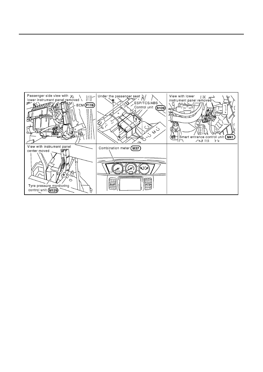
Component Parts and Harness Connector Location
EKS00ARU
MKIB0684E
CAN SYSTEM (TYPE 29)
LAN-139
[CAN]
C
D
E
F
G
H
I
J
L
M
A
B
LAN
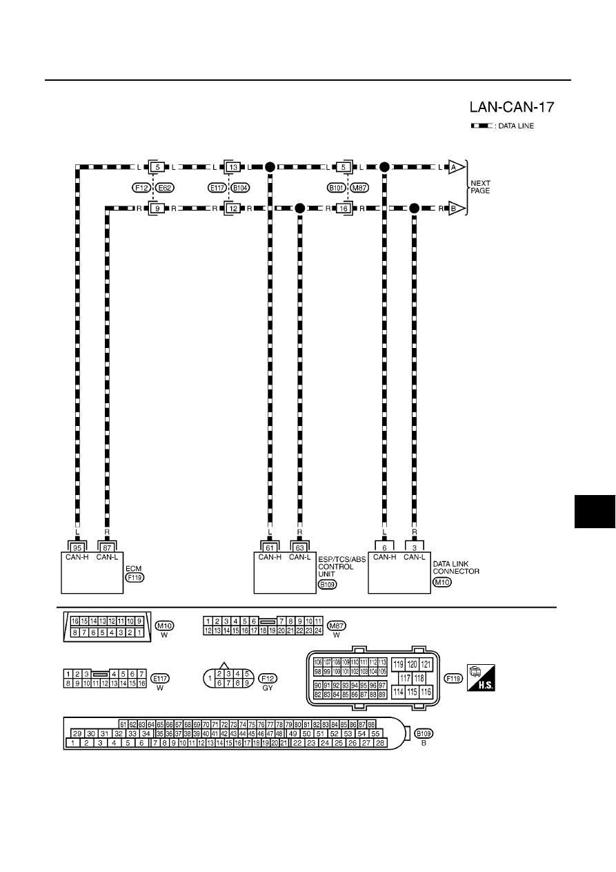
Wiring Diagram — CAN —
EKS00ARV
MKWA1723E
Нет комментариевНе стесняйтесь поделиться с нами вашим ценным мнением.
Текст