Nissan Primera P12. Manual — part 195
WARNING CHIME
DI-109
C
D
E
F
G
H
I
J
L
M
A
B
DI
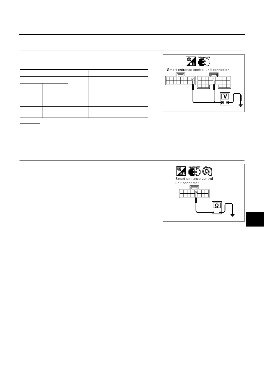
Power Supply and Ground Circuit Check
EKS009CW
1.
POWER SUPPLY CIRCUIT CHECK
1.
Disconnect smart entrance control unit connector.
2.
Check the following.
OK or NG
OK
>> GO TO 2.
NG
>>
●
10A fuse [NO. 10, located in fuse block (J/B)].
●
10A fuse [NO. 12, located in fuse block (J/B)].
●
Check harness for open or short between smart entrance control unit and fuse.
2.
GROUND CIRCUIT CHECK
Check continuity between smart entrance control unit harness con-
nector M43 terminal 53 (B) and ground.
OK or NG
OK
>> INSPECTION END.
NG
>> Check ground harness.
Terminals
Ignition switch position
(+)
(–)
OFF
ACC
ON
Connector
Terminal
(Wire color)
M42
29 (Y/G)
Ground
0V
0V
Battery
voltage
M43
56 (R/B)
Ground
Battery
voltage
Battery
voltage
Battery
voltage
MKIB0013E
Continuity should exist.
MKIB0014E
DI-110
WARNING CHIME
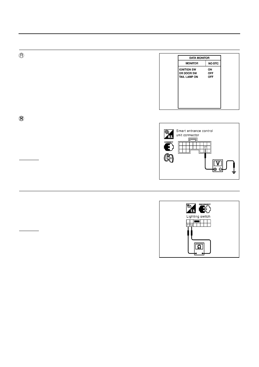
Lighting Switch Input Signal Check
EKS009CX
1.
CHECK LIGHTING SWITCH INPUT SIGNAL
With CONSULT-II
Check lighting switch (“TAIL LAMP ON”) in “DATA MONITOR” mode
with CONSULT-II.
Without CONSULT-II
Check voltage between smart entrance control unit harness connec-
tor M41 terminal 17 (R/G) and ground.
OK or NG
OK
>> Lighting switch is OK.
NG
>> GO TO 2.
2.
CHECK LIGHTING SWITCH POWER SUPPLY CIRCUIT FOR OPEN OR SHORT
1.
Disconnect lighting switch harness connector.
2.
Check voltage between lighting switch harness connector E115
terminal 11 (W/R: LHD models or R/G: RHD models) and
ground.
OK or NG
OK
>> GO TO 3.
NG
>> Check the following.
●
10A fuse (No. 32 located in the fuse and fusible link
box)
●
Harness for open or short between lighting switch and
fuse
When lighting switch is in
1st or 2nd position
: TAIL LAMP ON ON
When lighting switch is in
OFF position
: TAIL LAMP ON OFF
MKIB0192E
Condition of switch
Voltage [V]:
Lighting switch:
1st or 2nd
Approx. 12
Lighting switch:
OFF
0
MKIB0015E
Battery voltage should exist.
MKIB0700E
WARNING CHIME
DI-111
C
D
E
F
G
H
I
J
L
M
A
B
DI
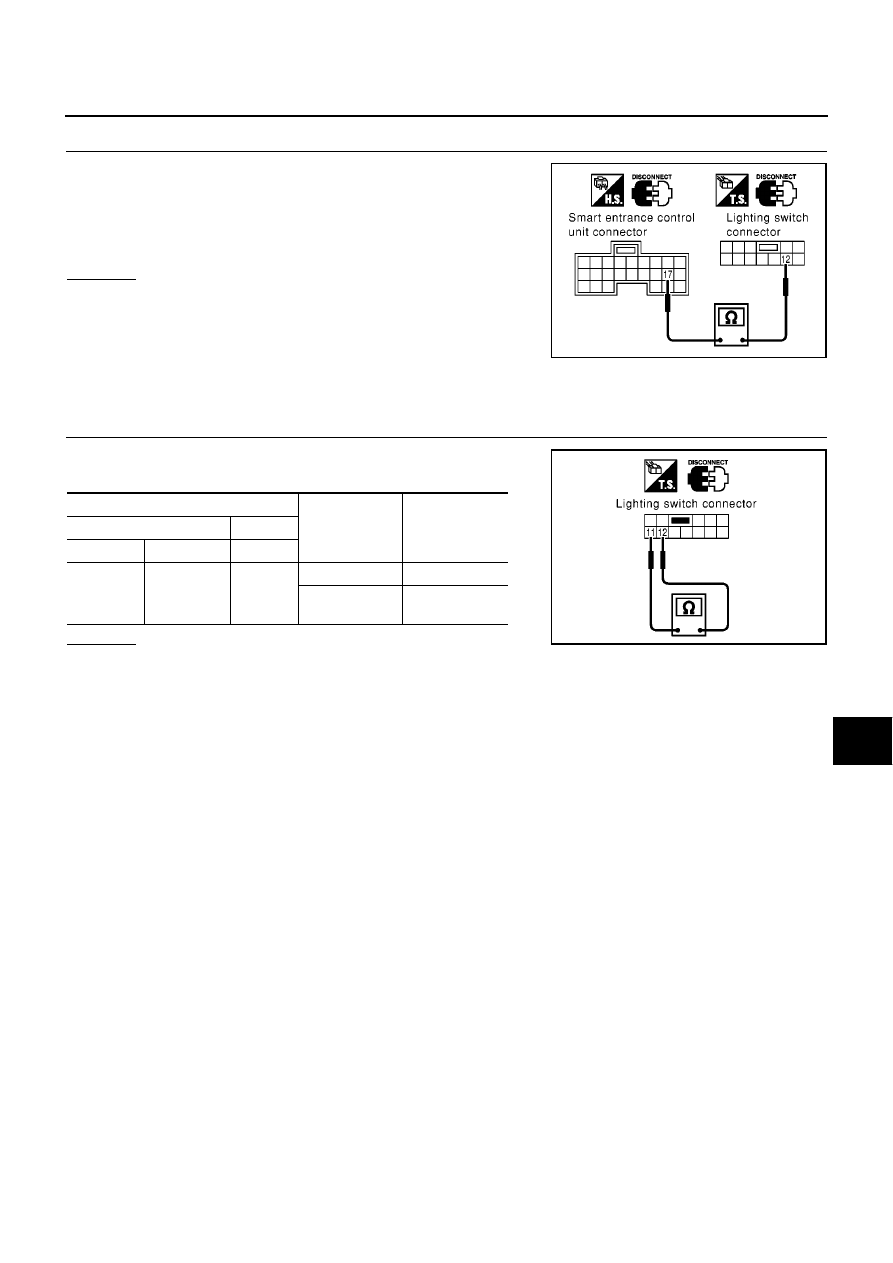
3.
CHECK LIGHTING SWITCH INPUT SIGNAL CIRCUIT FOR OPEN OR SHORT
Check harness continuity between lighting switch harness connector
E115 terminal 12 (W/R) and smart entrance control unit harness
connector M41 terminal 17 (W/R: LHD models or R/G: RHD mod-
els).
OK or NG
OK
>> GO TO 4.
NG
>> Check the following.
●
Harness for open or short between smart entrance
control unit and lighting switch.
●
Harness for open or short between smart entrance
control unit and lighting switch.
4.
CHECK LIGHTING SWITCH (DRIVER SIDE)
Check continuity between lighting switch connector E115 terminals
11 and 12.
OK or NG
OK
>> Lighting switch is OK.
NG
>> Replace lighting switch.
Continuity should exist.
MKIB0030E
Terminals
Condition
Continuity
(+)
(–)
Connector
Terminal
Terminal
E115
11
12
OFF position
No
1st or 2nd posi-
tion
Yes
MKIB0031E
DI-112
WARNING CHIME
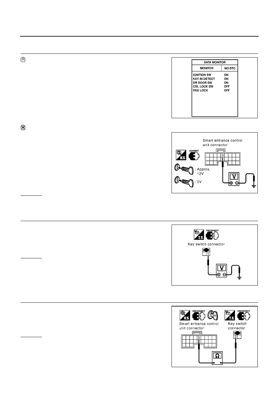
Key Switch Insert Signal Check
EKS009CY
1.
CHECK KEY SWITCH INPUT SIGNAL
With CONSULT-II
Check key switch (“KEY IN DETECT”) in “DATA MONITOR” mode
with CONSULT-II.
Without CONSULT-II
Check voltage between smart entrance control unit harness connec-
tor M41 terminal 5 (B/L) and ground.
OK or NG
OK
>> Key switch is OK.
NG
>> GO TO 2.
2.
CHECK KEY SWITCH POWER SUPPLY CIRCUIT FOR OPEN OR SHORT
1.
Disconnect key switch harness connector.
2.
Check voltage between key switch harness connector M30 ter-
minal 1 (R/B) and ground.
OK or NG
OK
>> GO TO 3.
NG
>> Check the following.
●
10A fuse [No. 32 located in fuse block (J/B)]
●
Harness for open or short between key switch and
fuse
3.
CHECK KEY SWITCH INPUT SIGNAL CIRCUIT FOR OPEN OR SHORT
Check harness continuity between key switch harness connector
M30 terminal 2 (B/R) and smart entrance control unit harness con-
nector M41 terminal 5 (B/R).
OK or NG
OK
>> GO TO 4.
NG
>> Repair or replace harness.
When key is inserted to
ignition key cylinder
: KEY IN DETECT ON
When key is removed from
ignition key cylinder
: KEY IN DETECT OFF
MKIB0193E
Condition of key switch
Voltage [V]
When key is inserted
to ignition key cylin-
der:
: Approx. 12
When key is removed
from ignition key cyl-
inder:
0
MKIB0701E
Battery voltage should exist.
MKIB0702E
Continuity should exist.
MKIB0703E
Нет комментариевНе стесняйтесь поделиться с нами вашим ценным мнением.
Текст