Nissan Primera P12. Manual — part 108
THEFT WARNING SYSTEM
BL-141
C
D
E
F
G
H
J
K
L
M
A
B
BL
SYMPTOM CHART
*1: Make sure the system is in the armed phase.
Power Supply and Ground Circuit Check
EIS005IX
1.
CHECK POWER SUPPLY CIRCUIT
1.
Turn ignition switch OFF.
2.
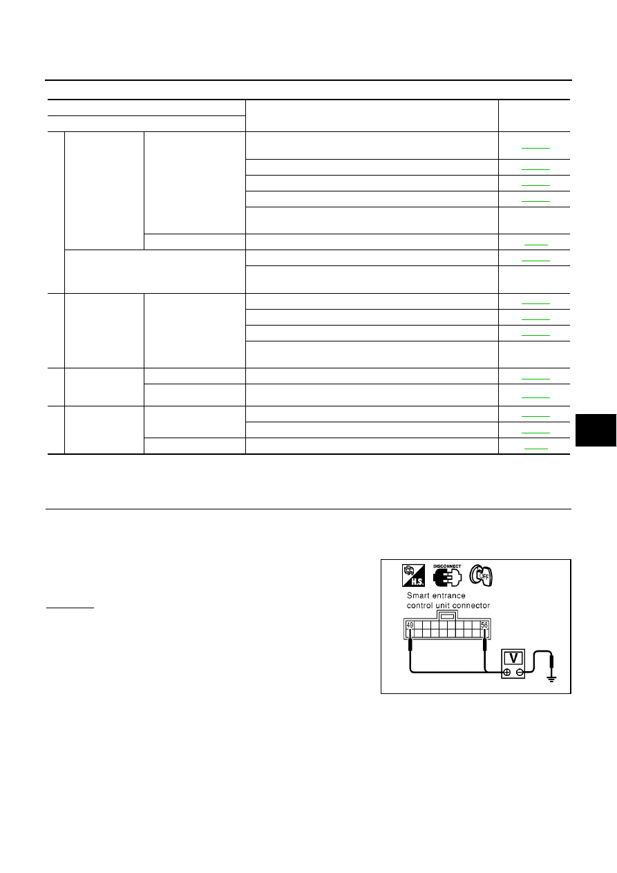
Disconnect smart entrance control unit connector.
3.
Check voltage between smart entrance control unit harness connector M43 terminal 49, 56 and ground.
OK or NG
OK
>> GO TO 2.
NG
>> Check the following.
●
40A fusible link (letter B, located in the fusible link and
fuse box)
●
10A fuse (No. 12, located in the fusible link and fuse
box)
●
Condition of circuit breaker-1
●
Harness for open or short smart entrance control unit power supply circuit.
PROCEDURE
Diagnostic procedure
Reference page
SYMPTOM
1
Theft warning
system cannot be
set by ····
AII items
Smart entrance control unit power supply and ground circuit
check
Door switch check
Hood switch check
Trunk room lamp switch or back door switch check
If the above systems are “OK”, replace smart entrance control
unit.
—
Remote controller
Check “MULTI-REMOTE CONTROL” system.
Security indicator does not turn “ON”.
Security indicator lamp check
If the above systems are “OK”, replace smart entrance control
unit.
—
2
*1
Theft warning
system does not
alarm when ····
Any door is opened.
Door switch check
Hood switch check
Trunk room lamp switch or back door switch check
If the above systems are “OK”, replace smart entrance control
unit.
—
3
Vehicle security
alarm does not
activate.
Horn alarm
Vehicle security horn alarm check
Hazard lamp alarm
Hazard lamp alarm check
4
Theft warning
system cannot be
canceled by ····
Ignition key
Key switch check
Check “NATS (NISSAN ANTI-THEFT SYSTEM)” system.
Remote controller
Check “MULTI-REMOTE CONTROL” system.
49 (W/L) - Ground
: Battery voltage
56 (R/B) - Ground
: Battery voltage
SIIA1564E
BL-142
THEFT WARNING SYSTEM
2.
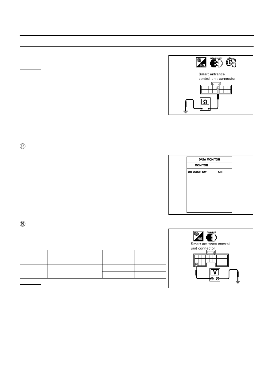
CHECK GROUND CIRCUIT
Check continuity between smart entrance control unit harness connector M43 terminal 53 and ground.
OK or NG
OK
>> Smart entrance control unit power supply and ground
circuit are OK.
NG
>> Check smart entrance control unit ground circuit for
open or short.
Door Switch Check
EIS005IY
DRIVER SIDE
1.
CHECK DOOR SWITCH INPUT SIGNAL
WITH CONSULT-II
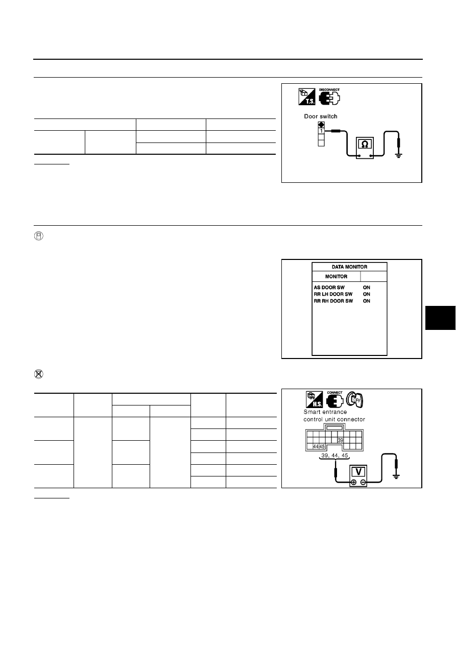
Check driver door switch signal (“DR DOOR SW”) in “DATA MONITOR” mode with CONSULT-II.
WITHOUT CONSULT-II
1.
Turn ignition switch OFF.
2.
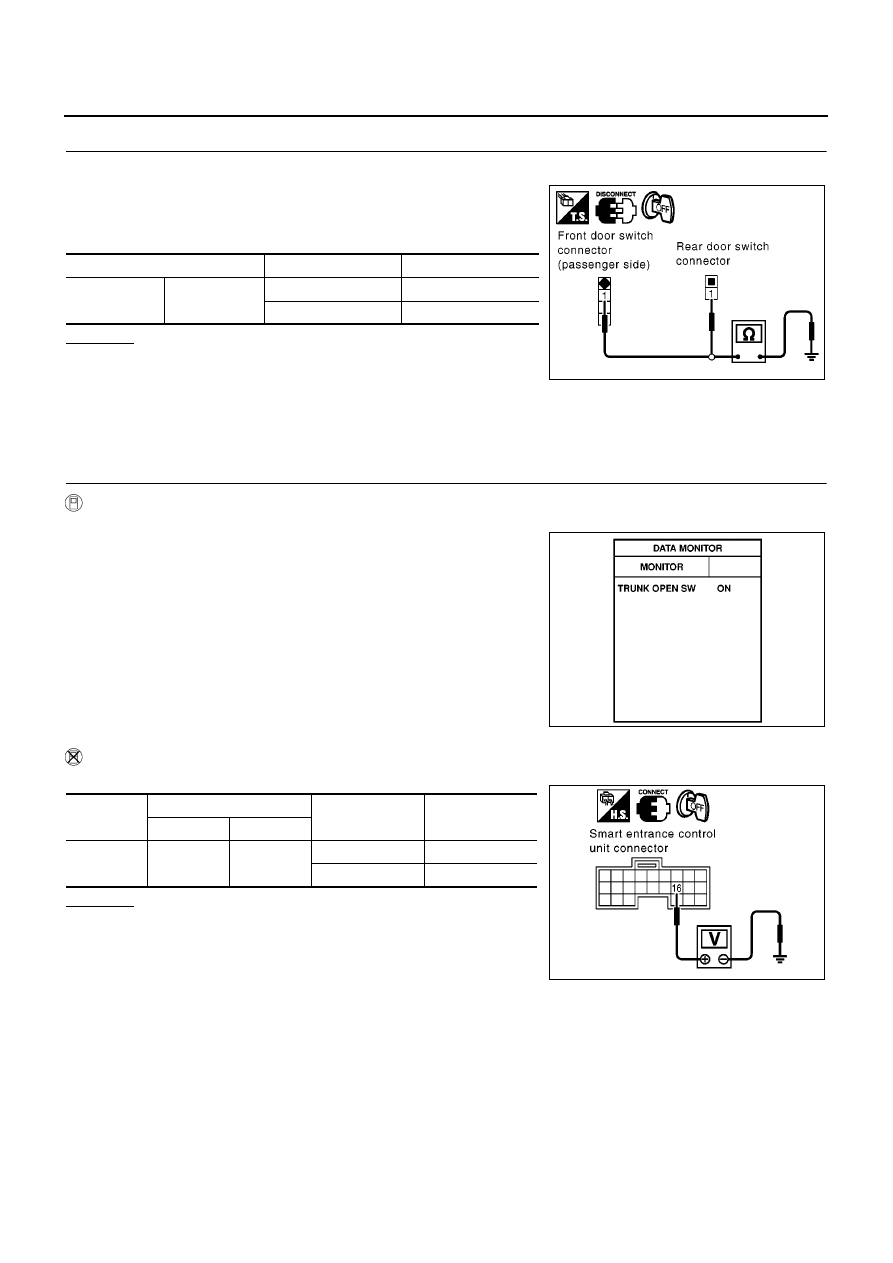
Check voltage between smart entrance control unit harness
connector and ground.
OK or NG
OK
>> Door switch (driver side) is OK.
NG
>> GO TO 2.
53 (B) - Ground
: Continuity should exist.
SIIA1565E
DR DOOR SW
Driver side door is open
: ON
Driver side door is closed
: OFF
MKIB0197E
Connector
Terminal (wire color)
Driver side door
condition
Voltage (V)
(Approx.)
( + )
( - )
M42
43 (R/W)
Ground
Open : (ON)
0
Closed : (OFF)
Battery voltage
MKIB0073E
THEFT WARNING SYSTEM
BL-143
C
D
E
F
G
H
J
K
L
M
A
B
BL
2.
CHECK DRIVER SIDE DOOR SWITCH
1.
Disconnect front door switch (driver side) connector.
2.
Check continuity between front door switch (driver side) terminal
1 and ground part of door switch.
OK or NG
OK
>> Check harness for open or short between smart
entrance control unit and front door switch (driver side).
NG
>> Replace front door switch (driver side).
EXCEPT DRIVER SIDE
1.
CHECK OTHER DOORS SWITCHES INPUT SIGNAL
WITH CONSULT-II
Check other doors switch signal (“AS DOOR SW”, “RR DOOR SW” or “RR RH DOOR SW”) in “DATA MONI-
TOR” mode with CONSULT-II.
WITHOUT CONSULT-II
Check voltage between smart entrance control unit harness connector and ground.
OK or NG
OK
>> Door switch OK.
NG
>> GO TO 2.
Terminal
Door switch
Continuity
1
Ground part of
door switch
Pushed
No
Released
Yes
PIIA3351E
Each DOOR SW
Each door is open
: ON
Each door is closed
: OFF
MKIB0199E
Item
Connector
Terminal (wire color)
Condition
Voltage (V)
(Approx.)
(+)
(
−
)
Rear door
LH or RH
M42
39 (BR/W)
Ground
Open
0
Closed
Battery voltage
Passenger
side
44 (L/OR)
Open
0
Closed
Battery voltage
Rear door
LH or RH
45 (R/Y)
Open
0
Closed
Battery voltage
MKIB0583E
BL-144
THEFT WARNING SYSTEM
2.
CHECK DOOR SWITCHES
1.
Turn ignition swtich OFF.
2.
Disconnect each door switches harness connector.
3.
Check continuity between door switch terminal 1 and ground
part of door switch.
OK or NG
OK
>> Check harness for open or short between smart
entrance control unit and door switch.
NG
>> Replace malfunction door switch.
Trunk Room Lamp Switch or Back Door Switch Check
EIS005IZ
TRUNK ROOM LAMP SWITCH
1.
CHECK TRUNK ROOM LAMP SWITCH INPUT SIGNAL
With CONSULT- II
Check door switch “TRUNK OPEN SWITCH” in “DATA MONITOR” mode with CONSULT- II.
Without CONSULT- II
Check voltage between smart entrance control unit harness connector and ground.
OK or NG
OK
>> Trunk room lamp switch is OK.
NG
>> GO TO 2
Terminal
Condition
Continuity
1
Ground part of
door switch
Pushed
No
Released
Yes
MKIB0584E
TRUNK OPEN SW
Trunk lid open
: ON
Trunk lid close
: OFF
SIIA1635E
Connector
Terminal (wire color)
Trunk lid
Voltage (V)
(Approx.)
(+)
(–)
M41
16 (G)
Ground
Closed
5
Open
0
SIIA1636E
Нет комментариевНе стесняйтесь поделиться с нами вашим ценным мнением.
Текст