Nissan Primera P12. Manual — part 510
GW-36
REAR WINDOW DEFOGGER
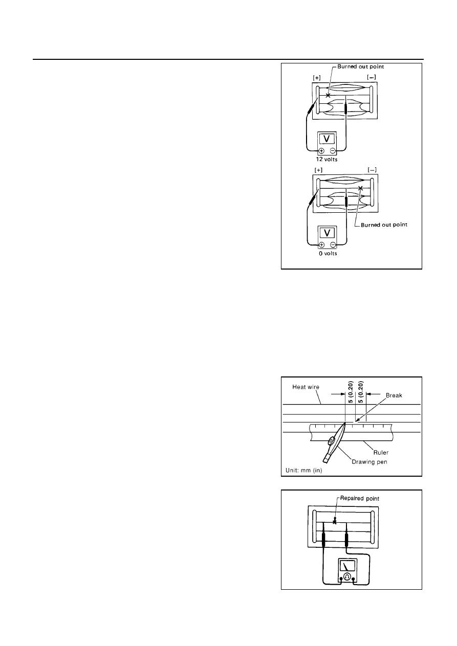
3.
If a filament is burned out, circuit tester registers 0 or battery
voltage.
4.
To locate burned out point, move probe to left and right along fil-
ament. Test needle will swing abruptly when probe passes the
point.
FILAMENT REPAIR
Repair Equipment
●
Conductive silver composition (Dupont NO. 4817 or equivalent)
●
Ruler 30 cm (11.8 in) long
●
Drawing pen
●
Heat gun
●
Alcohol
●
Cloth
Repairing Procedure
1.
Wipe broken heat wire and its surrounding area clean with a
cloth dampened alcohol.
2.
Apply a small amount of conductive silver composition to tip of
drawing pen.
Shake silver composition container before use.
3.
Place ruler on glass along broken line. Deposit conductive silver
composition on break with drawing pen. Slightly overlap existing
heat wire on both sides [preferably 5 mm (0.20 in)] of the break.
4.
After repair has been completed, check repaired wire for conti-
nuity. This check should be conducted 10 minutes after silver
composition is deposited.
Do not touch repaired area while test is being conducted.
SEL265
PIIA0215E
SEL012D

REAR WINDOW DEFOGGER
GW-37
C
D
E
F
G
H
J
K
L
M
A
B
GW
5.
Apply a constant stream of hot air directly to the repaired area
for approximately 20 minutes with a heat gun. A minimum dis-
tance of 3 cm (1.2 in) should be kept between repaired area and
hot air outlet.
If a heat gun is not available, let the repaired area dry for 24
hours.
SEL013D
GW-38
POWER WINDOW SYSTEM
POWER WINDOW SYSTEM
PFP:25401
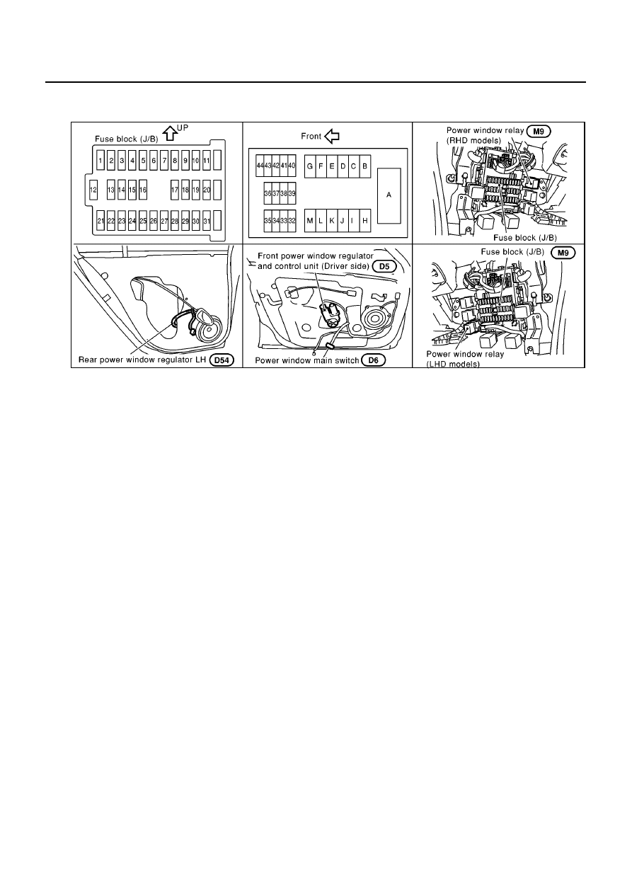
Component Parts and Harness Connector Location
EIS005K6
System Description
EIS005K7
Power is supplied at all times
●
through 40A fusible link (letter B , located in the fuse and fusible link box)
●
through circuit breaker-1 terminal 1
●
through circuit breaker-1 terminal 2
●
to power window relay terminal 5.
●
through circuit breaker-2 terminal 1
●
through circuit breaker-2 terminal 2
●
to front power window regulator and control unit terminal 3.
With ignition switch in ON or START position, power is supplied
●
through 10A fuse [No. 10, located in the fuse block (J/B)]
●
to power window relay terminal 1 or 2.
●
through 10A fuse [No. 20, located in the fuse block (J/B)]
●
to front power window regulator and control unit terminal 1.
Ground is supplied
●
to power window relay terminal 1 or 2
●
through body grounds M16, M50 and M70.
●
to front power window regulator and control unit terminal 4
●
through body grounds M16, M50 and M70.
●
to power window main switch terminal 3
●
through body grounds M16, M50 and M70.
The power window relay is energized and power is supplied
●
through power window relay terminal 3
●
to power window main switch terminal 2,
●
to passenger side power window switch terminal 2,
●
to rear power window switch LH and RH terminals 2 (LHD models).
When the unlock switch in the power window main switch is on, the rear power window relay (RHD models) is
energized and power is supplied
Ground is supplied
●
to rear power window switch LH and RH terminals 2.
MIIA0112E
POWER WINDOW SYSTEM
GW-39
C
D
E
F
G
H
J
K
L
M
A
B
GW
●
through rear power window relay terminal 3 (RHD models)
MANUAL OPERATION
Front Door (Driver Side)
WINDOW UP
When the driver's window switch in the power window main switch is pressed in the up position,
Ground is supplied
●
to driver side power window regulator and control unit terminal 5
●
through power window main switch terminal 4
●
through power window main switch terminal 3.
Then, the motor raises the window until the switch is released.
WINDOW DOWN
When the driver's window switch in the power window main switch is pressed in the down position,
Ground is supplied
●
to driver side power window regulator and control unit terminal 6
●
through power window main switch terminal 5
●
through power window main switch terminal 3.
Then, the motor lowers the window until the switch is released.
Front Door (Passenger Side)
NOTE:
Numbers in parentheses are terminal numbers, when power window switch is pressed in the UP and DOWN
positions respectively.
POWER WINDOW MAIN SWITCH OPERATION
Power is supplied
●
through power window main switch (6, 7)
●
to passenger side power window switch (6, 7).
Ground is supplied
●
to power window main switch terminal (6, 7)
●
through power window main switch terminal 3
●
through body ground M16, M50 and M70.
The subsequent operation is the same as the passenger side power window switch operation.
PASSENGER SIDE POWER WINDOW SWITCH OPERATION
Power is supplied
●
through passenger side power window switch (4, 5)
●
to passenger side power window regulator (2, 1).
Ground is supplied
●
to passenger side power window regulator (1, 2)
●
through passenger side power window switch (4, 5)
●
through passenger side power window switch (6, 7)
●
through power window main switch (6, 7).
Then, the motor raises or lowers the window until the switch is released.
Rear Door
Rear door windows will raise and lower in the same manner as passenger's door window.
AUTO OPERATION
The power window AUTO feature enables the driver to open or close the driver's window without holding the
window switch in the down or up position.
The AUTO feature operates on the driver's window.
POWER WINDOW LOCK
The power window lock is designed to lock operation of all windows except for driver's window.
When the lock switch is pressed to pressed to lock position, ground of the sub-switches in the power window
main switch is disconnected. This prevents the power window motors from operating.
Нет комментариевНе стесняйтесь поделиться с нами вашим ценным мнением.
Текст