Nissan Primera P12. Manual — part 428
EM-58
[YD]
CAMSHAFT
INSTALLATION
1.
Install the valve lifter and adjusting shim.
●
Make sure that these are installed in the same position as before the removal process.
2.
Install the camshaft.
●
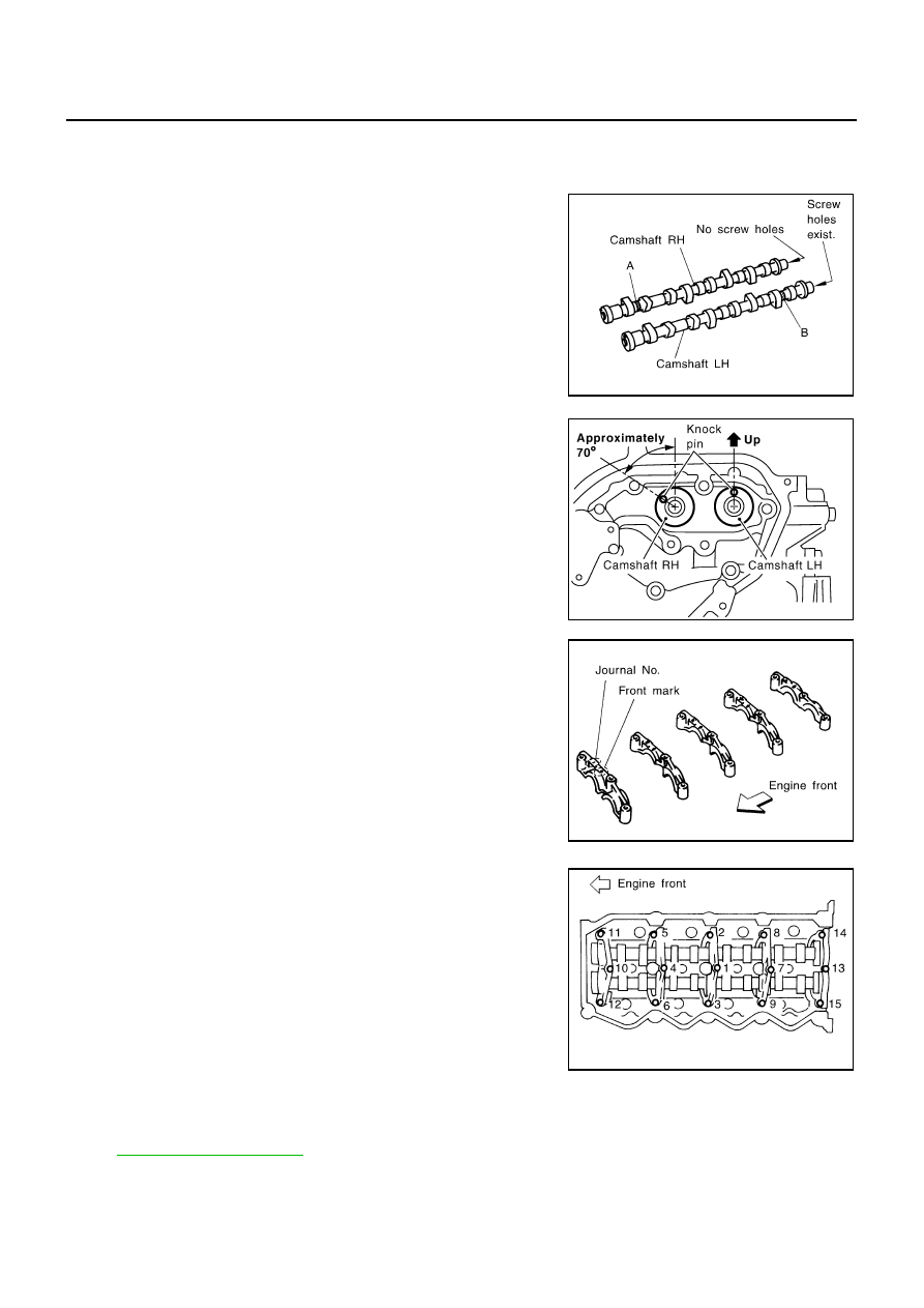
Identify camshafts by the paint position and screw hole at the
rear end.
●
Install so that dowel pins are positioned in the directions
shown in the figure.
3.
Install camshaft brackets.
●
Install correctly, identifying brackets by the journal No. and
front mark on top surface.
4.
Tighten bolts in the order shown in the figure according to the
following procedure:
a.
Tighten to 1.96 N·m (0.2 kg-m, 17 in-lb).
●
Make sure camshaft thrusting parts (on rear side) securely fit
in their mating parts on the cylinder head.
b.
Tighten to 5.88 N·m (0.6 kg-m, 52 in-lb).
c.
Tighten to 12 to 13 N·m (1.2 to 1.4 kg-m, 9 to 10 ft-lb).
5.
Install camshaft sprockets.
●
Camshaft sprockets are commonly used for RH and LH.
●
Align camshaft sprocket and dowel pin on camshaft, and
install.
●
Holding the hexagonal part of camshaft with a wrench, tighten bolt securing camshaft sprocket.
6.
Before installing spill tube after installing secondary timing chain, check and adjust valve clearance. Refer
to
.
7.
Hereafter, install in the reverse order of removal.
Camshaft
RH
: Paint is at position A without screw hole.
Camshaft LH
: Paint is at position B with screw hole.
JEM173G
SEM516G
JEM175G
JEM160G
CAMSHAFT
EM-59
[YD]
C
D
E
F
G
H
I
J
K
L
M
A
EM
Valve Clearance
EBS00SNX
INSPECTION
●
When the camshaft or parts in connection with valves are
removed or replaced, and a malfunction has occurred (poor
starting, idling, or other malfunction) due to the mis adjustment
of the valve clearance, inspect as follows.
●
Inspect and adjust when the engine is cool (at normal tempera-
ture).
●
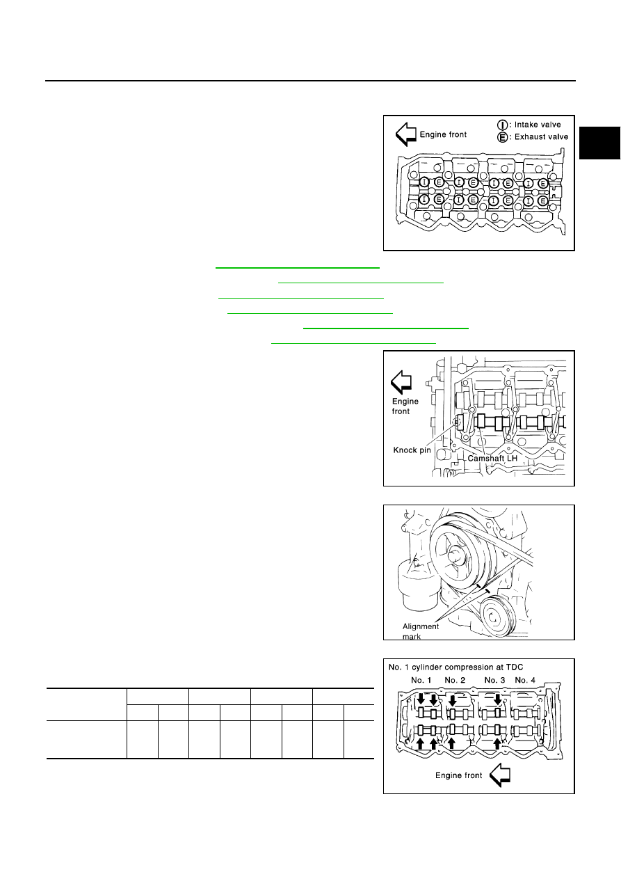
Be careful of the intake and exhaust valve arrangement. The
valve arrangement is different from that in a normal engine.
NOTE:
The camshafts have, alternately, either an intake valve or an
exhaust valve. (Refer to illustration)
1.
Drain engine coolant. Refer to
CO-8, "Changing Engine Coolant"
.
2.
Remove air duct and air inlet pipe. Refer to
EM-15, "Removal and Installation"
.
3.
Remove rocker cover. Refer to
EM-52, "Removal and Installation"
.
4.
Remove vacuum pump. Refer to
EM-35, "Removal and Installation"
.
5.
Remove injection tube and fuel injector. Refer to
EM-39, "Removal and Installation"
.
6.
Remove secondary timing chain. Refer to
EM-63, "Removal and Installation"
Check valve clearance while engine is cold and not running.
7.
Set the No. 1 piston to TDC on its compression stroke.
●
Turn crankshaft pulley clockwise so that the knock pin on
camshaft LH faces straight above. (No position indicator, etc.
is provided on the crankshaft pulley.)
8.
Put an alignment mark with paint, etc. on the crankshaft pulley
and on the oil pump as an angle indicator.
9.
While referring to the figure, measure the valve clearance
marked in the table below.
●
The injection order is 1-3-4-2.
SBIA0178E
SBIA0179E
JEM177G
Measuring point
No. 1
No. 2
No. 3
No. 4
INT
EXH
INT
EXH
INT
EXH
INT
EXH
When the No. 1
cylinder is in the
TDC
X
X
X
X
SBIA0180E
EM-60
[YD]
CAMSHAFT
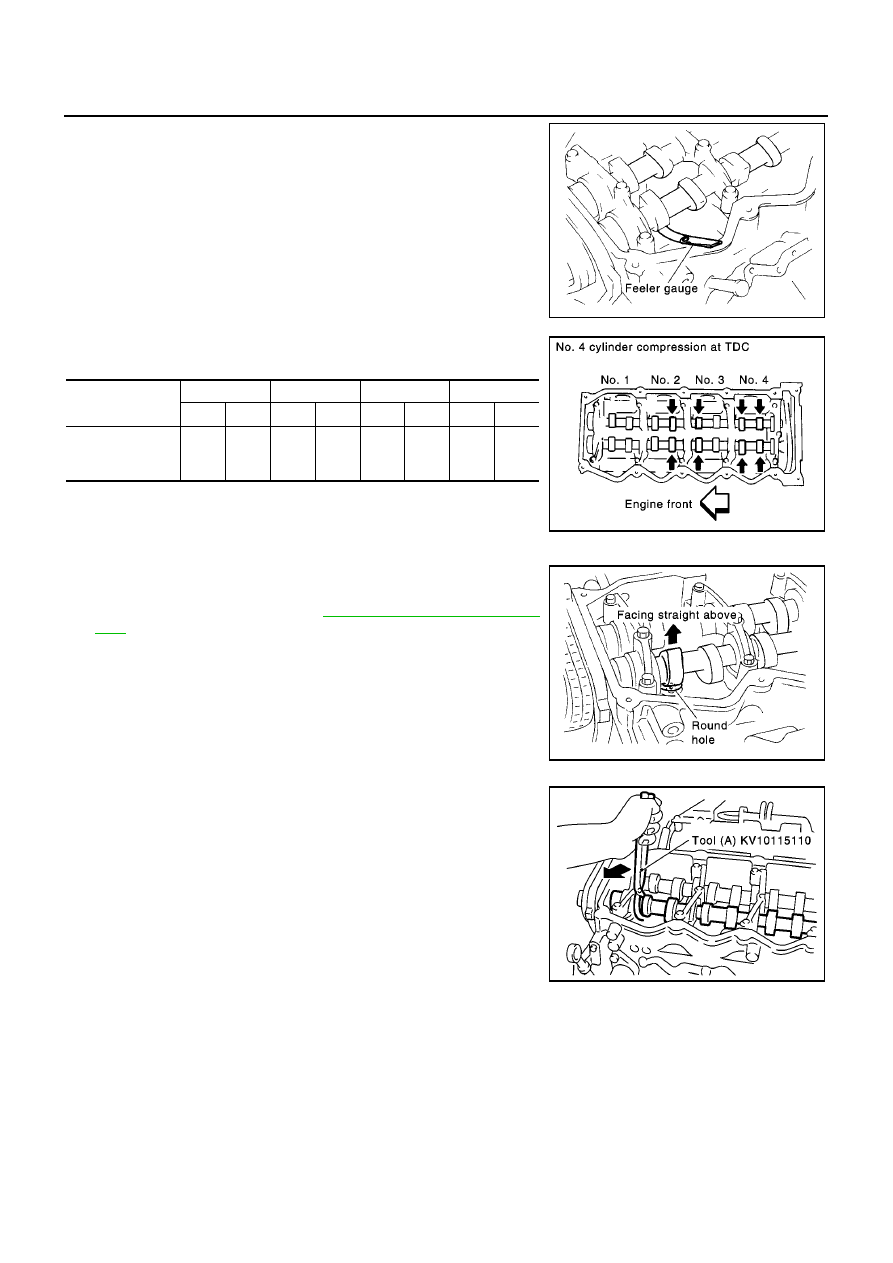
●
Measure the valve clearance using a fine feeler gauge when
the engine is cool (at normal temperature).
10. Set the No. 4 cylinder at TDC by rotating the crankshaft clock-
wise once.
11. While referring to the figure, measure the valve clearance
marked in the table below.
12. If the valve clearance is outside the specification, adjust as fol-
lows.
ADJUSTMENTS
●
Remove the adjusting shim for parts which are outside the spec-
ified valve clearance.
1.
Remove the spill tube. Refer to
.
2.
Extract the engine oil on the upper side of the cylinder head (for
the air blowing in step 7).
3.
Rotate the crankshaft to face the camshaft for adjusting shims
that are to be removed upward.
4.
Grip the camshaft with camshaft pliers, them using the camshaft
as a support point, push the adjusting shim downward to com-
press the valve spring.
CAUTION:
Do not damage the camshaft, cylinder head and the outer
circumference of the valve lifter.
Valve clearance (Cold):
Standard:
Intake
: 0.24 - 0.32 mm (0.0094 - 0.0126 in)
Exhaust
: 0.26 - 0.34 mm (0.0102 - 0.0134 in)
SBIA0181E
Measuring point
No. 1
No. 2
No. 3
No. 4
INT
EXH
INT
EXH
INT
EXH
INT
EXH
When the No. 4
cylinder is in the
TDC
X
X
X
X
SBIA0182E
SBIA0183E
SBIA0184E
CAMSHAFT
EM-61
[YD]
C
D
E
F
G
H
I
J
K
L
M
A
EM
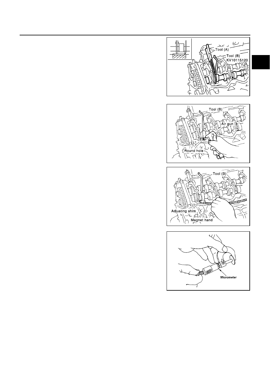
5.
With the valve spring in a compressed state, remove the cam-
shaft pliers by securely setting the outer circumference of the
valve lifter with the end of the lifter stopper.
●
Hold the lifter stopper by hand until the shim is removed.
CAUTION:
Do not retrieve the camshaft pliers forcefully, as the cam-
shaft will be damaged.
6.
Move the rounded hole of the adjusting shim to the front with a
very thin screwdriver or like that.
●
When the adjusting shim on the valve lifter will not rotate
smoothly, restart from step 4 to release the end of the lifter
stopper from touching the adjusting shim.
7.
Remove the adjusting shim from the valve lifter by blowing air
through the rounded hole of the shim with an air gun.
CAUTION:
To prevent any remaining oil from being blown around,
thoroughly wipe the area clean and wear protective gog-
gles.
8.
Remove the adjusting shim by using a magnetic hand.
9.
Measure the thickness of the adjusting shim using a micrometer.
●
Measure near the center of the shim (the part that touches the
camshaft).
10. Select the new adjusting shim from the following methods.
SBIA0185E
SBIA0186E
SBIA0187E
Calculation method of the adjusting shim thickness:
R = Thickness of removed shim
N = Thickness of new shim
M = Measured valve clearance
Intake
N = R + [M - 0.28 mm (0.0010 in)]
Exhaust
N = R + [M - 0.30 mm (0.0118 in)]
FEM032
Нет комментариевНе стесняйтесь поделиться с нами вашим ценным мнением.
Текст