Nissan Primera P12. Manual — part 483
FL-18
FUEL TANK (F9Q)
6.
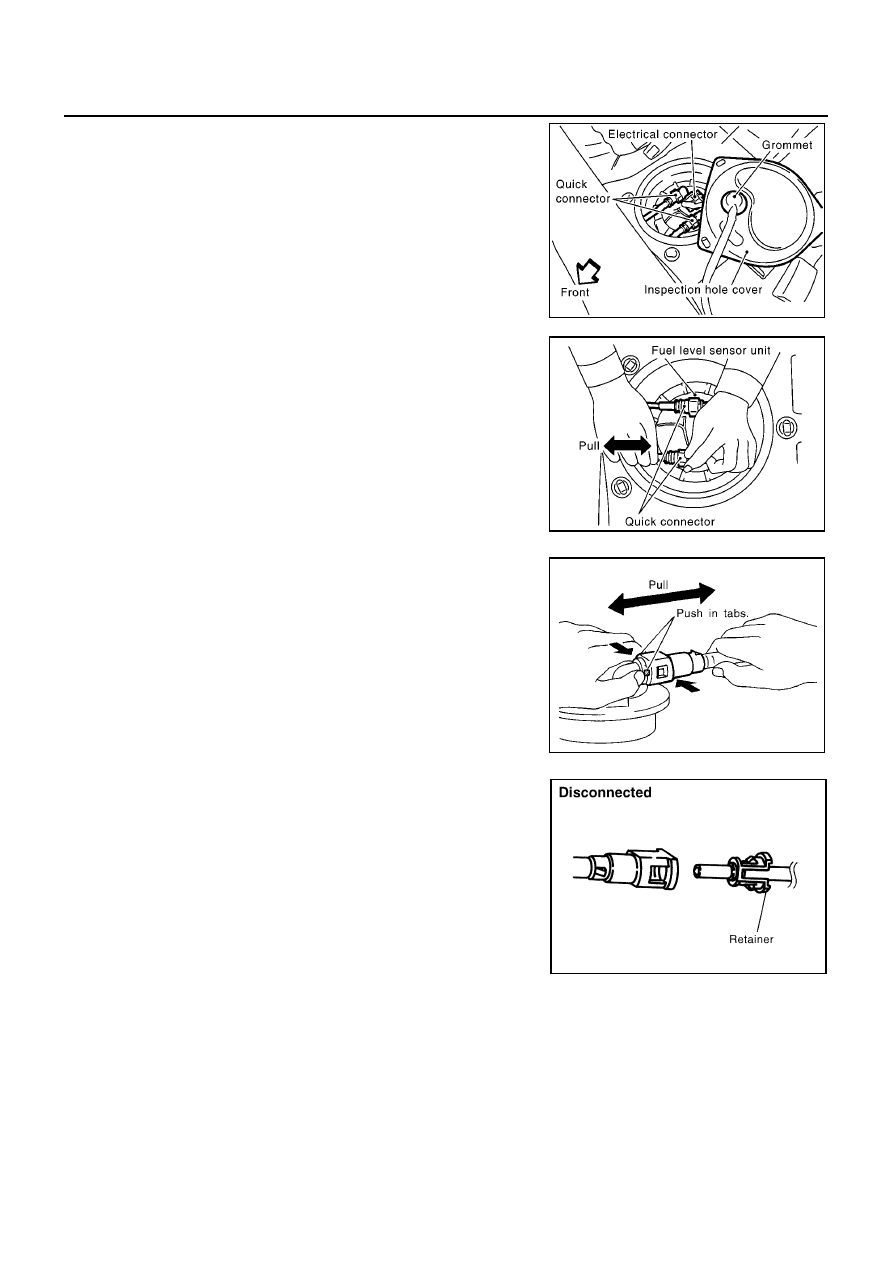
Disconnect electrical connector.
7.
Disconnect the quick connector as follows.
●
Hold the connector while pushing in tabs, and pull out the
tube.
CAUTION:
●
The tube can be removed when the tabs are completely depressed. Do not twist it more than
necessary.
●
Do not use any tools to remove the quick connector.
●
Keep the resin tube away from heat. Be especially careful when welding near the tube.
●
Prevent acid liquid such as battery electrolyte etc. from getting on the resin tube.
●
Do not bend or twist the tube during installation and removal.
●
Only when the tube is replaced, remove the remaining retainer.
●
When the tube is replaced, also replace the retainer with a new one.
MBIB0522E
MBIB0523E
SFE562A
JFE628A
FUEL TANK (F9Q)
FL-19
C
D
E
F
G
H
I
J
K
L
M
A
FL
8.
Remove exhaust center tube. Refer to
EX-2, "Removal and Installation"
.
9.
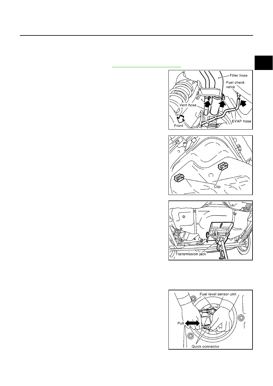
From rear left area of fuel tank, remove filler hose, vent hose,
and fuel check valve.
CAUTION:
To prevent fuel from flowing out, install a blind cap immedi-
ately after the fuel hose is disconnected.
10. Lower the fuel tank by 70 to 80 mm (2.76 to 3.15 in), remove the
nuts and clips holding the protector, and then remove the protec-
tor.
●
To remove the clips shown in the figure.
NOTE:
Always replace after every disassembly.
11. Set a suitable transmission jack under fuel tank.
12. Remove fuel tank mounting band bolts while supporting fuel
tank.
13. Remove fuel tank.
INSTALLATION
Install in the reverse order of removal. Connect the quick connector as follows:
●
Insert tube into the center of the connector until you hear a click.
●
After connecting quick connector, make sure the connection is
firmly made using the following method.
●
Pull on the fuel tube and connector to make sure they are firmly
connected.
●
Start the engine, increase engine speed and verify that there are
no leaks.
Retainer color:
Red (Feed hose side)
White (Return hose side)
MBIB0858E
MBIB0859E
MBIB0529E
MBIB0523E

FL-20
SERVICE DATA AND SPECIFICATIONS (SDS)
SERVICE DATA AND SPECIFICATIONS (SDS)
PFP:00030
Standard and Limit
EBS00SJ2
Tightening Torque
EBS00SJ3
Unit: N·m (kg-m, ft-lb)
Unit: N·m (kg-m, in-lb)*
Fuel tank capacity (YD engine models)
Approx. 62
(13 - 5/8 lmp gal)
Fuel tank tightening band (YD engine models)
37.0 - 49.0 (3.8 - 4.9, 28 - 36)
Fuel filler tube (YD engine models)
11.0 - 14.0 (1.2 - 1.4, 9 - 10)
Fuel tank protector (YD engine models)
4.25 - 5.75 (0.44 - 0.58, 38 - 50)*
Lock ring
31.0 - 35.0 (3.2 - 3.5, 23 - 25)

FSU-1
FRONT SUSPENSION
E SUSPENSION
CONTENTS
C
D
F
G
H
I
J
K
L
M
SECTION
A
B
FSU
FRONT SUSPENSION
PRECAUTIONS . . . . . . . . . . . . . . .. 2
Caution . . . . . . . . . . . . . . . . . . 2
Precautions for Brake System . . . . . . . . .. 2
PREPARATION . . . . . . . . . . . . . . ... 3
Special Service Tools . . . . . . . . . . . ... 3
Commercial Service Tools . . . . . . . . . . 3
NOISE, VIBRATION AND HARSHNESS (NVH)
TROUBLESHOOTING . . . . . . . . . . . . 4
NVH Troubleshooting Chart . . . . . . . . . . 4
FRONT SUSPENSION ASSEMBLY . . . . . . ... 5
Components . . . . . . . . . . . . . . . . 5
On-Vehicle Inspection and Service . . . . . . .. 6
LOOSENESS, BACKLASH AND DAMAGE OF
MOUNTING PARTS AND CONNECTIONS . . .. 6
Wheel Alignment . . . . . . . . . . . . . .. 6
DESCRIPTION . . . . . . . . . . . . . .. 6
PRELIMINARY INSPECTION . . . . . . . ... 6
INSPECTION OF CAMBER, CASTER, AND
KINGPIN INCLINATION ANGLES . . . . . . 6
STEERING ANGLE INSPECTION . . . . . . 7
COIL SPRING AND SHOCK ABSORBER . . . . . 8
Removal and Installation . . . . . . . . . . .. 8
REMOVAL . . . . . . . . . . . . . . . . 8
INSTALLATION . . . . . . . . . . . . . . 8
Disassembly and Assembly . . . . . . . . . . 8
DISASSEMBLY . . . . . . . . . . . . . . 8
INSPECTION AFTER DISASSEMBLY . . . . . 8
ASSEMBLY . . . . . . . . . . . . . . ... 9
TRANSVERSE LINK . . . . . . . . . . . . . 10
Removal and Installation . . . . . . . . . . 10
STABILIZER BAR . . . . . . . . . . . . . . 11
Removal and Installation . . . . . . . . . . 11
FRONT SUSPENSION MEMBER . . . . . . . . 12
Removal and Installation . . . . . . . . . . 12
REMOVAL . . . . . . . . . . . . . . ... 12
INSTALLATION . . . . . . . . . . . . ... 12
UPPER LINK . . . . . . . . . . . . . . . . 13
Removal and Installation . . . . . . . . . . 13
THIRD LINK . . . . . . . . . . . . . . . .. 14
Removal and Installation . . . . . . . . . . 14
Нет комментариевНе стесняйтесь поделиться с нами вашим ценным мнением.
Текст