Nissan Primera P12. Manual — part 478
FAX-22
FRONT DRIVE SHAFT
8.
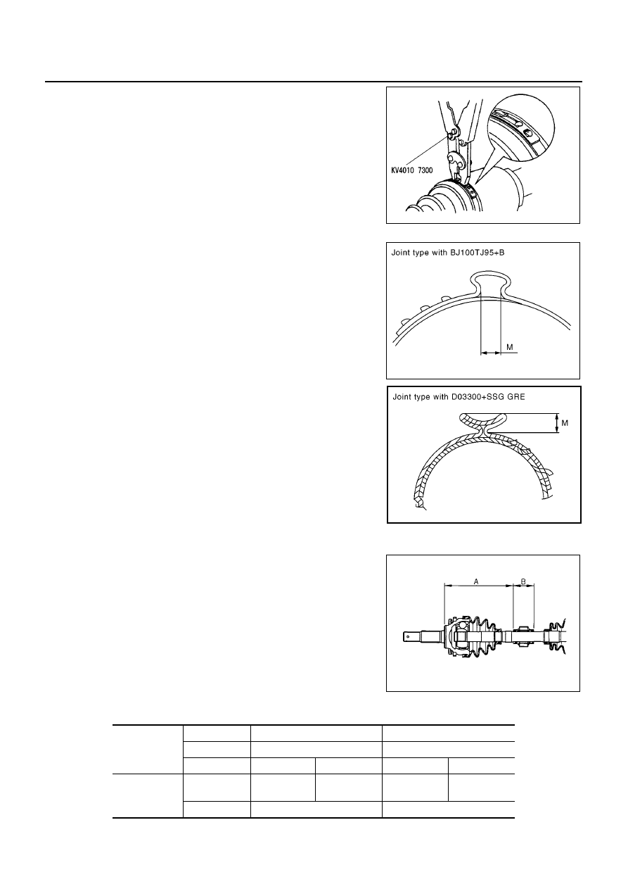
As shown in the figure, secure the big and small ends of the
boot with new boot bands.
9.
Rotate joint part and confirm that mounting position of boot does
not deviate. When it deviates, mount a new boot band again.
CAUTION:
When fixing boot band, fix so that the M diameter on the
drawing becomes as follows.
Dynamic Damper
●
When dynamic damper has been removed, secure with bands
as shown in the figure so that measurements from fixed-joint
side are as listed below.
CAUTION:
Discard the old dynamic damper: replace with a new one.
Mounting Dimensions
SDIA0876J
M diameter (small ends)
D03300+SSG GRE
: 5mm (0.20 in)
BJ100TJ95+B
: 1.0 - 4.0 (0.04 - 0.16 in)
MDIA0071E
MDIA0072E
FAC0156D
Applied model
Engine
YD22DDTi
F9Q
Transaxle
6-MT
6-MT
Drive shaft
RH
LH
RH
LH
Dimension
mm (in)
“A”
227 - 233
(8.94 - 9.17)
177 - 183
(6.97 - 7.20)
227 - 233
(8.94 - 9.17)
207 - 213
(8.15 - 8.39)
“B”
70 (2.76)
70 (2.76)
SERVICE DATA AND SPECIFICATIONS (SDS)
FAX-23
C
E
F
G
H
I
J
K
L
M
A
B
FAX
SERVICE DATA AND SPECIFICATIONS (SDS)
PFP:00030
Wheel Bearing
EDS0015R
Drive Shaft
EDS0015S
Drive type
2WD
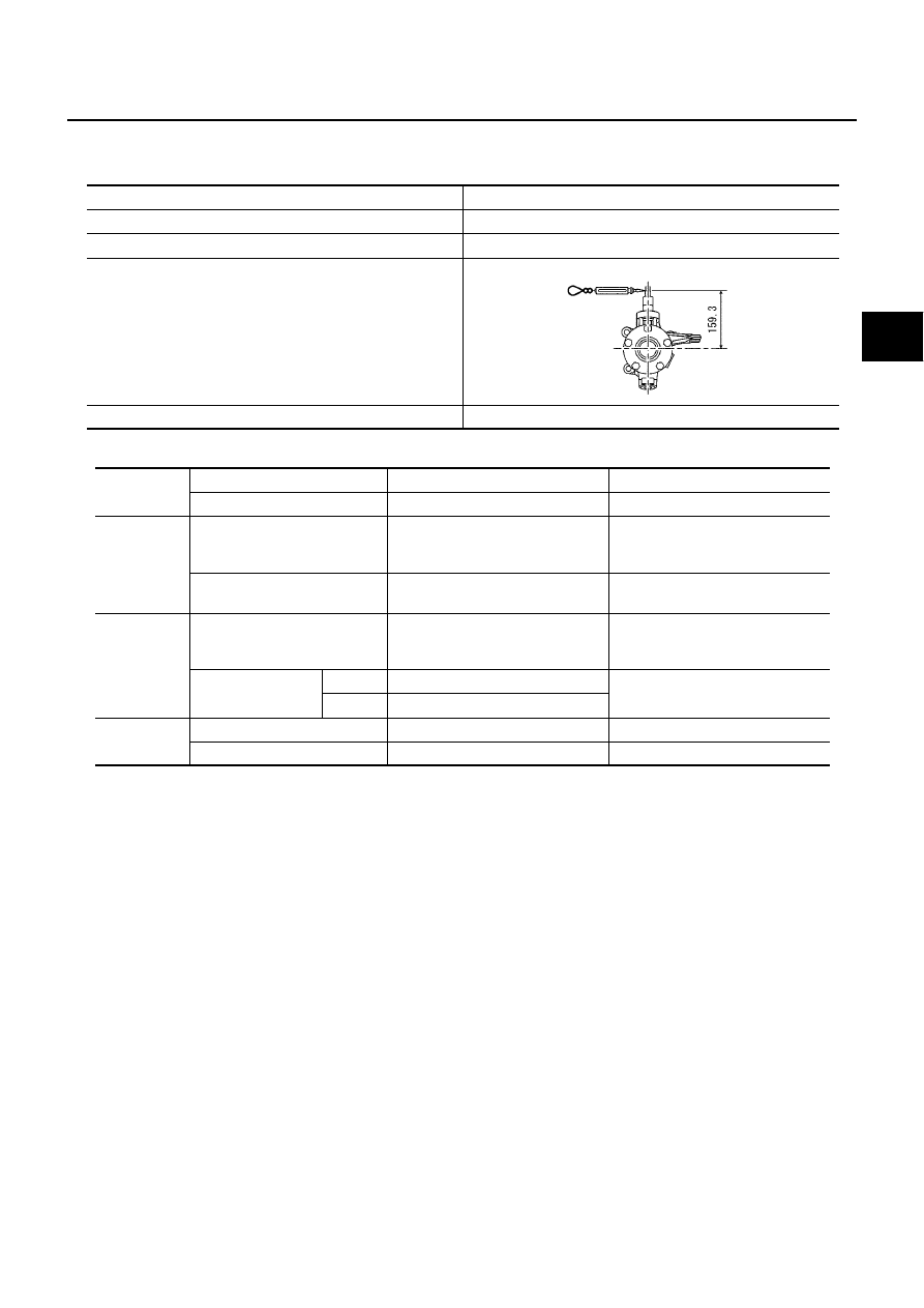
Rotation torque
1.645 N·m (0.168 kg-m,15 in-lb) or less
Spring balance reading
10.3 N (1.05 kg, 2.3 lb) or less
Installation location of spring scale
Axial end play
0.045 - 0.065 mm (0.0018 - 0.0026 in) or less
SDIA0221J
Applied
model
Engine
YD22DDTi
F9Q
Transaxle
6-MT
6-MT
Joint type
Transaxle side
39711-AV610
39711-AV615
(D03300+SSG)
39771-AW312
39711-AW312
(TJ95B0230)
Wheel side
39211-AV610
(D03300+SSG)
39211-AW300
(BJ100LACB0258)
Grease
capacity
g (oz)
Transaxle side
215.0 - 225.0
(7.58 - 7.94)
SSG grease
160 - 180
(5.64 - 6.35)
Wheel side
Joint
40 - 50 (1.41 - 1.76)
130 - 150
(4.59 - 5.29)
Boot
70 - 80 (2.47 - 2.82)
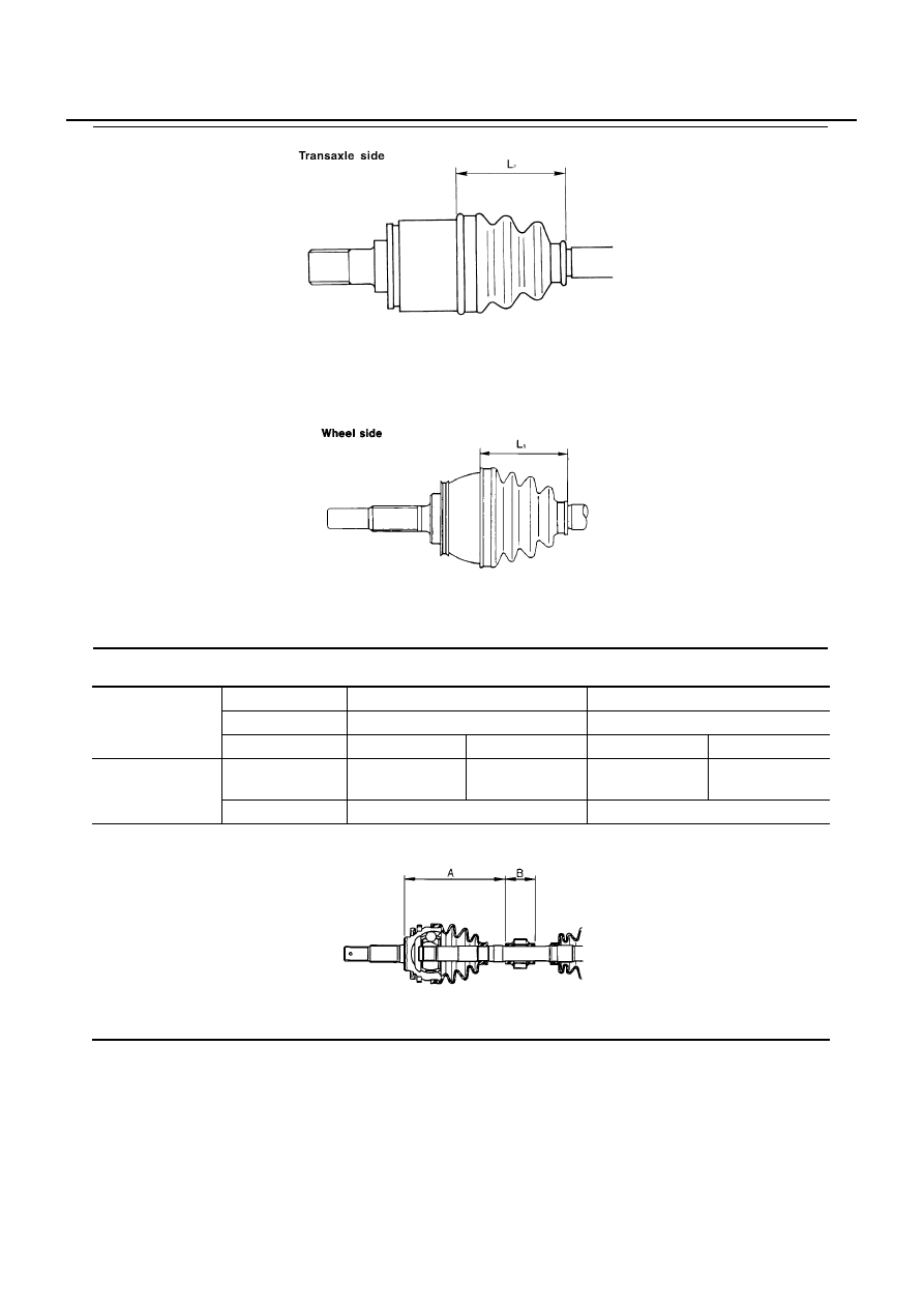
Boot length
mm (in)
Transaxle side “L
2
”
105 (4.13)
Wheel side “L
1
”
105 - 106 (4.13 - 4.17)
FAX-24
SERVICE DATA AND SPECIFICATIONS (SDS)
Dynamic Damper
EDS0015T
SFA961AA
SFA962A
Applied model
Engine
YD22DDTi
F9Q
Transaxle
6-MT
6-MT
Drive shaft
RH
LH
RH
LH
Dimension
mm (in)
“A”
227 - 233
(8.94 - 9.17)
177 - 183
(6.97 - 7.20)
227 - 233
(8.94 - 9.17)
207 - 213
(8.15 - 8.39)
“B”
70 (2.76)
70 (2.76)
FAC0156D

FL-1
FUEL SYSTEM
B ENGINE
CONTENTS
C
D
E
F
G
H
I
J
K
L
M
SECTION
A
FL
FUEL SYSTEM
PREPARATION . . . . . . . . . . . . . . ... 2
Commercial Service Tools . . . . . . . . . . 2
FUEL SYSTEM . . . . . . . . . . . . . . ... 3
Checking Fuel Lines . . . . . . . . . . . . . 3
General Precautions . . . . . . . . . . . . 3
FUEL FILTER (YD22DDTI) . . . . . . . . . . . 4
Removal and Installation . . . . . . . . . . .. 4
Air Bleeding . . . . . . . . . . . . . . . .. 5
Draining Water . . . . . . . . . . . . . . . 5
FUEL FILTER (F9Q) . . . . . . . . . . . . ... 6
Removal and Installation . . . . . . . . . . .. 6
Draining Water . . . . . . . . . . . . . . . 7
FUEL FILTER CHECK . . . . . . . . . . .. 7
Air Bleeding . . . . . . . . . . . . . . . .. 7
FUEL LEVEL SENSOR UNIT (YD22DDTI) . . . . 8
Removal and Installation . . . . . . . . . . .. 8
REMOVAL . . . . . . . . . . . . . . . . 8
INSTALLATION . . . . . . . . . . . . ... 10
INSPECTION AFTER INSTALLATION . . . . 10
FUEL LEVEL SENSOR UNIT (F9Q) . . . . . . . 11
Removal and Installation . . . . . . . . . . 11
REMOVAL . . . . . . . . . . . . . . ... 11
INSTALLATION . . . . . . . . . . . . ... 13
FUEL TANK (YD22DDTI) . . . . . . . . . . .. 14
Removal and Installation . . . . . . . . . . 14
REMOVAL . . . . . . . . . . . . . . ... 14
INSTALLATION . . . . . . . . . . . . ... 15
INSPECTION AFTER INSTALLATION . . . . 16
FUEL TANK (F9Q) . . . . . . . . . . . . . 17
Removal and Installation . . . . . . . . . . 17
REMOVAL . . . . . . . . . . . . . . ... 17
INSTALLATION . . . . . . . . . . . . ... 19
SERVICE DATA AND SPECIFICATIONS (SDS) . .. 20
Standard and Limit . . . . . . . . . . . . .. 20
Tightening Torque . . . . . . . . . . . . ... 20
Нет комментариевНе стесняйтесь поделиться с нами вашим ценным мнением.
Текст