Nissan Primera P12. Manual — part 120
BRAKE MASTER CYLINDER
BR-19
C
D
E
G
H
I
J
K
L
M
A
B
BR
7.
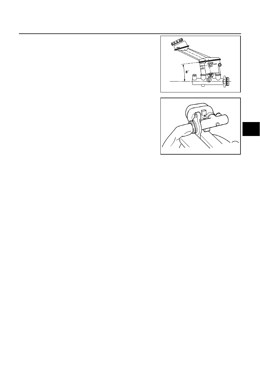
Install the reservoir tank to the master cylinder.
CAUTION:
Pay attention to the orientation of the reservoir tank.
8.
Tighten the flange of the cylinder body in the figure.
CAUTION:
●
Using the copper plate or closes to cover the flange for
fixing base.
●
Pay attention to the orientation of the cylinder body.
●
Secure with chamfered pin insert hole on the cylinder
body facing upward.
9.
Install reservoir tank to the cylinder body. Tilt reservoir tank as shown in the figure and insert mounting pin.
When mounting pin passes through pinhole in the master cylinder, return reservoir tank to the upright
position. Push mounting pin all the way through the opposite pinhole in the reservoir tank.
CAUTION:
●
Do not reuse reservoir tank mounting pin.
●
Do not reuse reservoir tank.
●
Be sure to insert pin from the chamfered pinhole on the cylinder body.
MFIA0005E
MFIA0003E
BR-20
BRAKE BOOSTER
BRAKE BOOSTER
PFP:47200
On-Vehicle Inspection and Service
EFS002V4
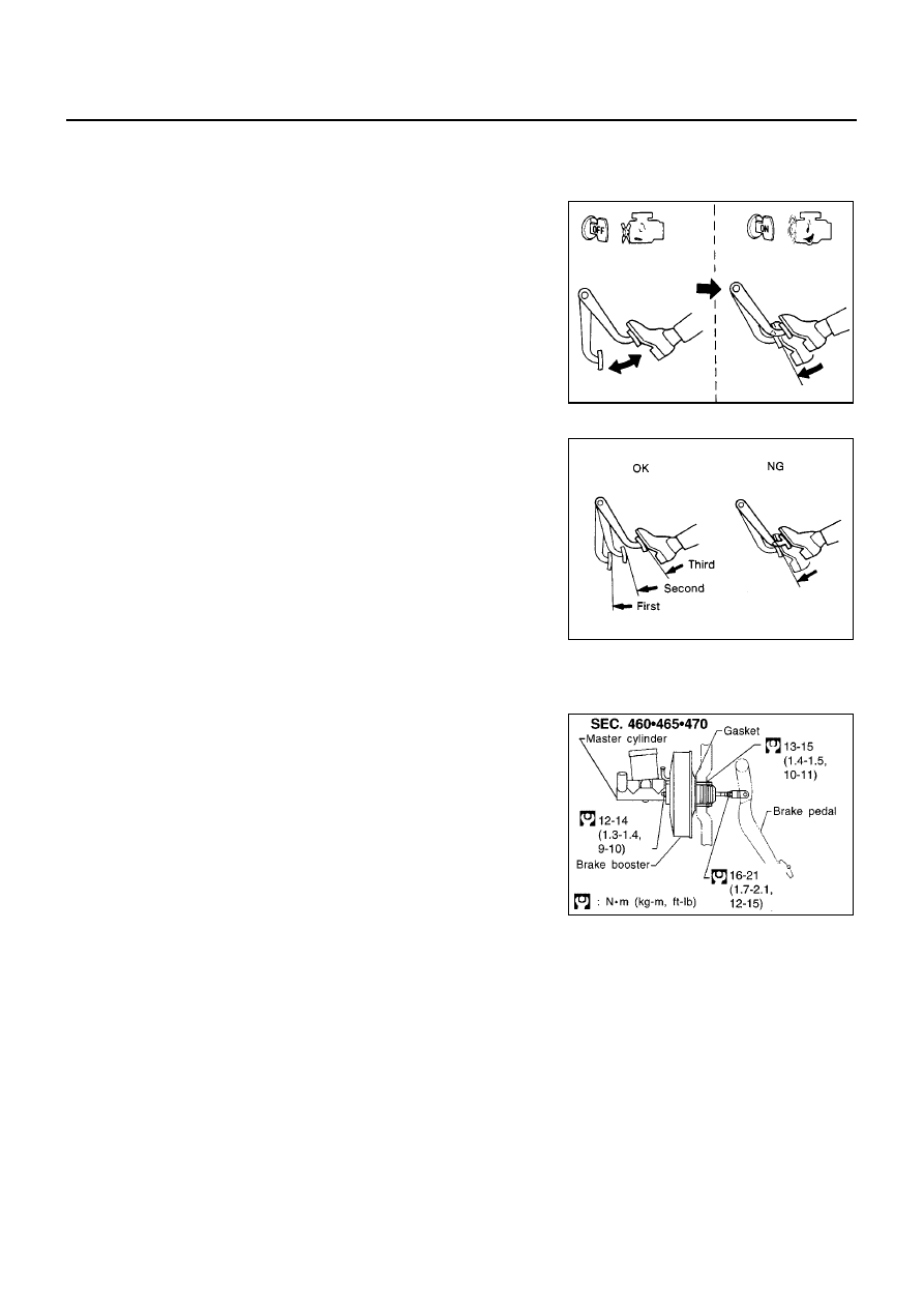
FUNCTION INSPECTION
With the engine stopped, discharge stored vacuum by depressing
brake pedal several times at 5 second intervals. With the brake
pedal fully depressed, start the engine. Confirm that clearance
between brake pedal and the floor panel decreases when engine
vacuum stabilizes.
AIRTIGHTNESS INSPECTION
●
Run the engine at idle for approximately 1 minute. Stop it after
applying vacuum to the booster. Depress the brake pedal sev-
eral times with normal force to discharge the stored vacuum.
Confirm that clearance between brake pedal and the floor panel
gradually increases as the brake pedal is depressed.
●
Run the engine. Depress and hold the brake pedal then stop the
engine. Keep the brake pedal depressed for 30 seconds or more
and make sure the pedal stroke does not change.
Removal and Installation
EFS002V5
REMOVAL
CAUTION:
●
Be careful not to deform or bend brake piping while remov-
ing and installing the brake booster.
●
Replace clevis pin if it is damaged.
●
Be careful not to damage brake booster stud bolt threads. If
brake booster is tilted or inclined during installation, the
dash panel may damage the threads.
●
Be sure to install the check valve in the correct orientation.
1.
Remove vacuum piping from the brake booster.
2.
Remove master cylinder.
3.
Remove snap pin and clevis pin on passenger compartment cle-
vis. Remove input rod from the brake pedal.
4.
Remove brake booster and brake pedal assembly mounting nuts.
5.
Remove booster assembly from the engine compartment.
INSPECTION AFTER REMOVAL
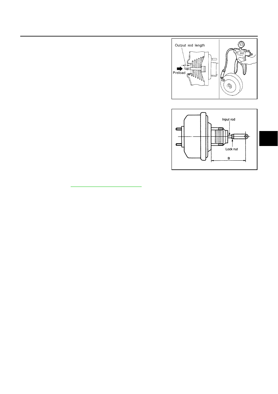
Output rod length inspection
1.
Using a handy vacuum pump, apply a vacuum of -66.7 kPa (-500 mmHg, -19.69 inHg) to the brake
booster.
BRA0037D
SBR365AA
SFIA0139E
BRAKE BOOSTER
BR-21
C
D
E
G
H
I
J
K
L
M
A
B
BR
2.
Place an output rod gauge in the master cylinder. Rotate the
screw until the gauge contacts the primary piston.
3.
Turn output rod gauge upside down to secure A. Adjust it with B
until clearance between output rod and screw is 0 mm.
INSTALLATION
1.
Loosen lock nut to adjust input rod length so that length “B” (in
the figure) satisfies the specified value.
2.
After adjusting “B”, temporarily tighten lock nut to install booster
assembly to vehicle.
3.
Connect brake pedal to input rod clevis.
4.
Connect brake pedal assembly mounting nuts and tighten to the
specified torque.
5.
Connect master cylinder to the booster assembly.
6.
Adjust brake pedal height and play.
7.
Tighten input rod lock nut to the specified torque.
8.
Bleed air. Refer to
BR-10, "Bleeding Brake System"
.
Reference value at vacuum of -66.7 kPa (-500 mmHg, -
19.69 inHg):
Without ESP
: 10.4 mm (0.409 in)
With ESP
: -6.2 mm (0.244 in)
SBR208E
Length “B” standard
: 125 mm (4.92 in)
SGIA0060E
BR-22
VACUUM LINES
VACUUM LINES
PFP:41920
Removal and Installation
EFS002V6
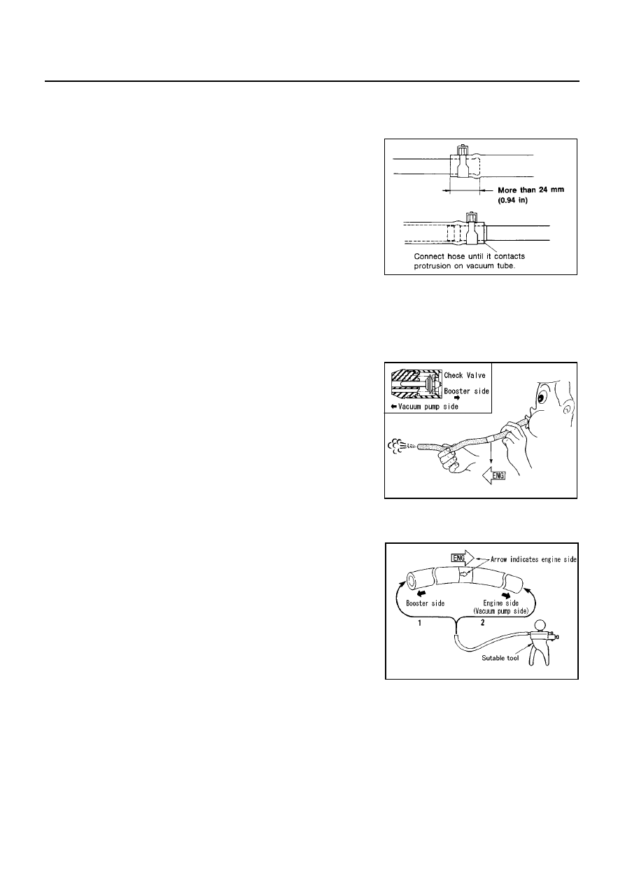
CAUTION:
●
Because vacuum hose contains a check valve, it must be
installed in the correct orientation. Refer to the stamp or
label to confirm correct installation. The brake booster will
not operate normally if the hose is installed in the wrong
direction.
●
Insert the vacuum hose for at least 24 mm (0.94 in).
●
Never use lubricating oil during assembly.
Inspection
EFS002V7
VISUAL INSPECTION
Check for improper assembly, damage and aging.
CHECK VALVE INSPECTION
Quick Inspection
The check valve is incorporated in the vacuum hose. Blow air into
vacuum hose to inspect the check valve. The check valve is normal
when air can only be blown in from the booster side.
CAUTION:
If air can blow both ways through the vacuum hose, replace
hose and check valve as a set.
Airtightness Inspection
Use a hand-held vacuum pump to check.
SBR225B
SFIA0209E
SFIA0210E
When connected to booster side (1):
Vacuum decrease should be within 1.3 kPa (10 mmHg, 0.39 inHg) for 15 seconds
under a vacuum of -66.7 kPa (-500 mmHg, -19.69 inHg)
When connected to engine side (2):
No vacuum will be applied
Нет комментариевНе стесняйтесь поделиться с нами вашим ценным мнением.
Текст