Nissan Primera P12. Manual — part 697
WT-2
PRECAUTIONS
PRECAUTIONS
PFP:00011
Precautions for Supplemental Restraint System (SRS) “AIR BAG” and “SEAT
BELT PRE-TENSIONER”
EES001A2
The Supplemental Restraint System such as “AIR BAG” and “SEAT BELT PRE-TENSIONER”, used along
with a front seat belt, helps to reduce the risk or severity of injury to the driver and front passenger for certain
types of collision. Information necessary to service the system safely is included in the SRS and SB section of
this Service Manual.
WARNING:
●
To avoid rendering the SRS inoperative, which could increase the risk of personal injury or death
in the event of a collision which would result in air bag inflation, all maintenance must be per-
formed by an authorized NISSAN/INFINITI dealer.
●
Improper maintenance, including incorrect removal and installation of the SRS, can lead to per-
sonal injury caused by unintentional activation of the system. For removal of Spiral Cable and Air
Bag Module, see the SRS section.
●
Do not use electrical test equipment on any circuit related to the SRS unless instructed to in this
Service Manual. SRS wiring harnesses can be identified by yellow and/or orange harnesses or
harness connectors.
Wiring Diagrams and Trouble Diagnosis
EES001A3
When you read wiring diagrams, refer to the following:
●
Refer to
GI-14, "How to Read Wiring Diagrams"
in GI section
●
Refer to
for power distribution circuit in PG section
When you perform trouble diagnosis, refer to the following:
●
Refer to
GI-11, "HOW TO FOLLOW TEST GROUPS IN TROUBLE DIAGNOSES"
in GI section
●
Refer to
GI-24, "How to Perform Efficient Diagnosis for an Electrical Incident"
in GI section
NOISE, VIBRATION AND HARSHNESS (NVH) TROUBLESHOOTING
WT-3
C
D
F
G
H
I
J
K
L
M
A
B
WT
NOISE, VIBRATION AND HARSHNESS (NVH) TROUBLESHOOTING
PFP:00003
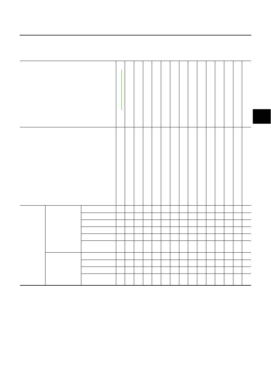
NVH Troubleshooting Chart
EES001A4
Use the chart below to help you find the cause of the symptom. If necessary, repair or replace these parts.
×
: Applicable
Reference page
Re
fe
r
to
—
—
—
—
—
—
N
V
H
in
M
T
,
A
T
and
C
V
T
s
ect
ion.
N
V
H
in
F
AX
and
FSU
s
ec
ti
ons
.
N
V
H
inR
A
X
a
n
dR
S
U
s
e
c
ti
o
n
s
.
R
e
fe
r
to
T
YRES
in
th
is
ch
ar
t.
Re
fe
r
to
R
OAD
W
HEEL
in
th
is
c
h
a
rt
.
N
V
H
in
F
AX
sect
ion.
N
V
Hi
n
B
Rs
e
c
ti
o
n
.
N
V
H
in
P
S
s
ect
ion.
Possible cause and SUSPECTED PARTS
Ou
t-
o
f-r
o
u
n
d
Im
bal
ance
In
co
rr
ect
tyr
e
p
re
ssur
e
U
n
e
v
en
ti
re
w
ear
D
e
fo
rm
a
ti
o
n
o
r
d
am
age
N
o
n
-un
if
or
mi
ty
In
c
o
rr
e
c
t
tir
e
s
iz
e
DIFFERETIAL
FRONT
AXLE
A
ND
F
R
O
N
T
S
USPENSION
REAR
AXLE
A
ND
RE
AR
SUSPENSION
TYRES
ROAD
WHEEL
D
R
IV
E
SH
AF
T
BRAKE
STEERING
Symptom
TYRES
Noise
×
×
×
×
×
×
×
×
×
×
×
×
×
Shake
×
×
×
×
×
×
×
×
×
×
×
×
Vibration
×
×
×
×
×
×
Shimmy
×
×
×
×
×
×
×
×
×
×
×
×
Judder
×
×
×
×
×
×
×
×
×
×
×
Poor quality ride
or handling
×
×
×
×
×
×
×
×
×
ROAD WHEEL
Noise
×
×
×
×
×
×
×
×
×
×
Shake
×
×
×
×
×
×
×
×
×
Shimmy, judder
×
×
×
×
×
×
×
×
Poor quality ride
or handling
×
×
×
×
×
×
WT-4
ROAD WHEEL
ROAD WHEEL
PFP:40300
Inspection
EES001A5
ALUMINUM WHEEL
1.
Check tyres for wear and improper inflation.
2.
Check wheels for deformation, cracks and other damage. If
deformed, remove wheel and check wheel runout.
a.
Remove tire from aluminum wheel and mount on a tire balance
machine.
b.
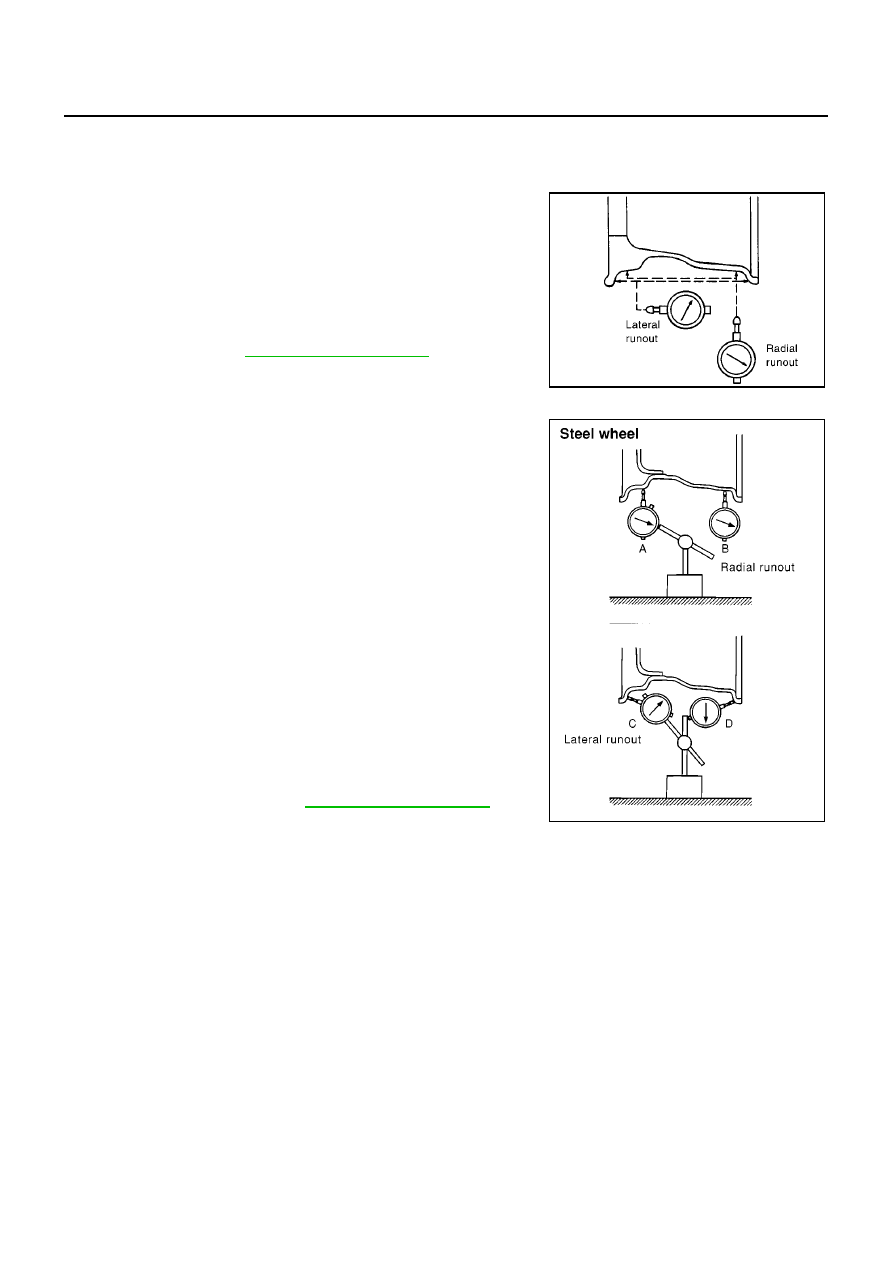
Set dial indicator as shown in the illustration.
STEEL WHEEL
1.
Check tyres for wear and improper inflation.
2.
Check wheels for deformation, cracks and other damage. If
deformed, remove wheel and check wheel runout.
a.
Remove tyre from steel wheel and mount wheel on a tyre bal-
ance machine.
b.
Set two dial indicators as shown in the illustration.
c.
Set each dial indicator to 0.
d.
Rotate wheel and check dial indicators at several points around
the circumference of the wheel.
e.
Calculate runout at each point as shown below.
f.
Select maximum positive runout value and the maximum nega-
tive value.
Add the two values to determine total runout.
In case a positive or negative value is not available, use the
maximum value (negative or positive) for total runout.
If the total runout value exceeds the limit, replace steel wheel.
Wheel runout (Dial indicator value):
Refer to
SFA975B
Radial runout = (A + B)/2
: 0.5 mm (0.020 in)
Lateral runout = (C + D)/2
: 0.8 mm (0.031 in)
Wheel runout:
Refer to
MDIA0001E
ROAD WHEEL AND TYRE ASSEMBLY
WT-5
C
D
F
G
H
I
J
K
L
M
A
B
WT
ROAD WHEEL AND TYRE ASSEMBLY
PFP:40312
Balancing Wheels (Bonding Weight Type)
EES001A6
REMOVAL
1.
Remove inner and outer balance weights from the road wheel.
CAUTION:
Be careful not to scratch the road wheel during removal procedures.
2.
Using releasing agent, remove double-faced adhesive tape from the road wheel.
CAUTION:
Be careful not to scratch the road wheel during removal.
●
After removing double-faced adhesive tape, wipe clean traces of releasing agent from the road wheel.
WHEEL BALANCE ADJUSTMENT
●
If a tyre balance machine has adhesion balance weight mode settings and drive-in weight mode setting,
select and adjust a drive-in weight mode suitable for road wheels.
1.
Set road wheel on wheel balancer using the center hole as a guide. Start the tyre balance machine.
2.
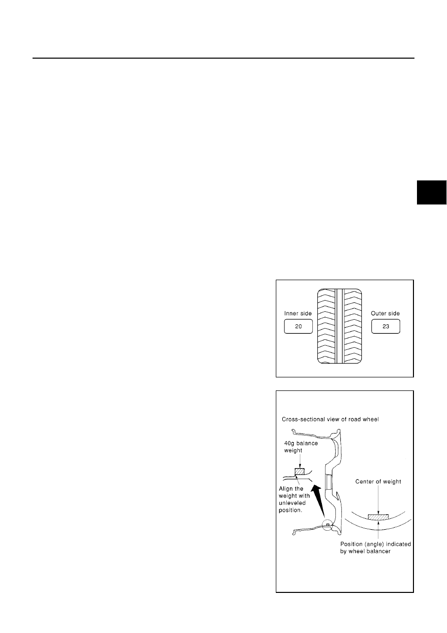
When inner and outer unbalance values are shown on the wheel balancer indicator, multiply outer unbal-
ance value by 5/3 to determine balance weight that should be used. Select the outer balance weight with
a value closest to the calculated value above and install it to the designated outer position of, or at the
designated angle in relation to the road wheel.
CAUTION:
●
Do not install the inner balance weight before installing the outer balance weight.
●
Before installing the balance weight, be sure to clean the mating surface of the road wheel.
Indicated unbalance value
×
5/3 = balance weight to be installed
Calculation example:
23 g (0.81 oz)
×
5/3 = 38.33 g (1.35 oz) = 40 g (1.41 oz) balance
weight (closer to calculated balance weight value)
Note that balance weight value must be closer to the calculated bal-
ance weight value.
Example:
37.4 = 35 g (1.23 oz)
37.5 = 40 g (1.41 oz)
●
Attach weight as shown in figure.
●
When attaching weight to road wheel, align it with step on rear
surface of wheel, as shown in figure. Attach so that center of
weight and position (angle) of wheel balancer indicator are
aligned.
●
Do not attach more than 2 adhesive weights.
SMA054D
MDIA0002E
Нет комментариевНе стесняйтесь поделиться с нами вашим ценным мнением.
Текст