Nissan Primera P12. Manual — part 297
ON BOARD DIAGNOSTIC (OBD) SYSTEM
EC-373
[YD (WITHOUT EURO-OBD)]
C
D
E
F
G
H
I
J
K
L
M
A
EC
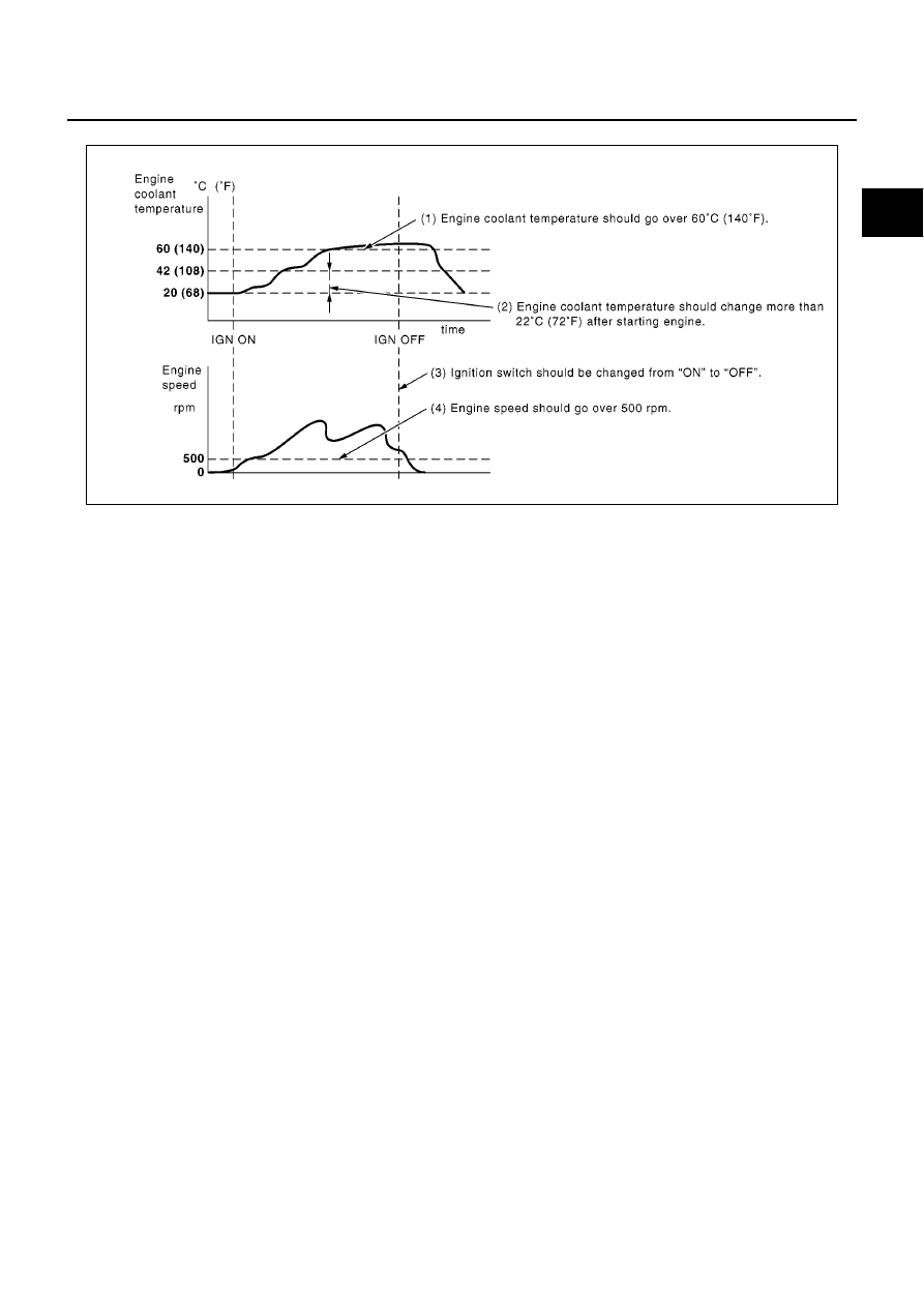
Driving Pattern A
●
The A counter will be cleared when the malfunction is detected regardless of (1) - (4).
●
The A counter will be counted up when (1) - (4) are satisfied without the same malfunction.
●
The DTC will not be displayed after the A counter reaches 40.
MBIB0923E
EC-374
[YD (WITHOUT EURO-OBD)]
TROUBLE DIAGNOSIS
TROUBLE DIAGNOSIS
PFP:00004
Trouble Diagnosis Introduction
EBS015RN
INTRODUCTION
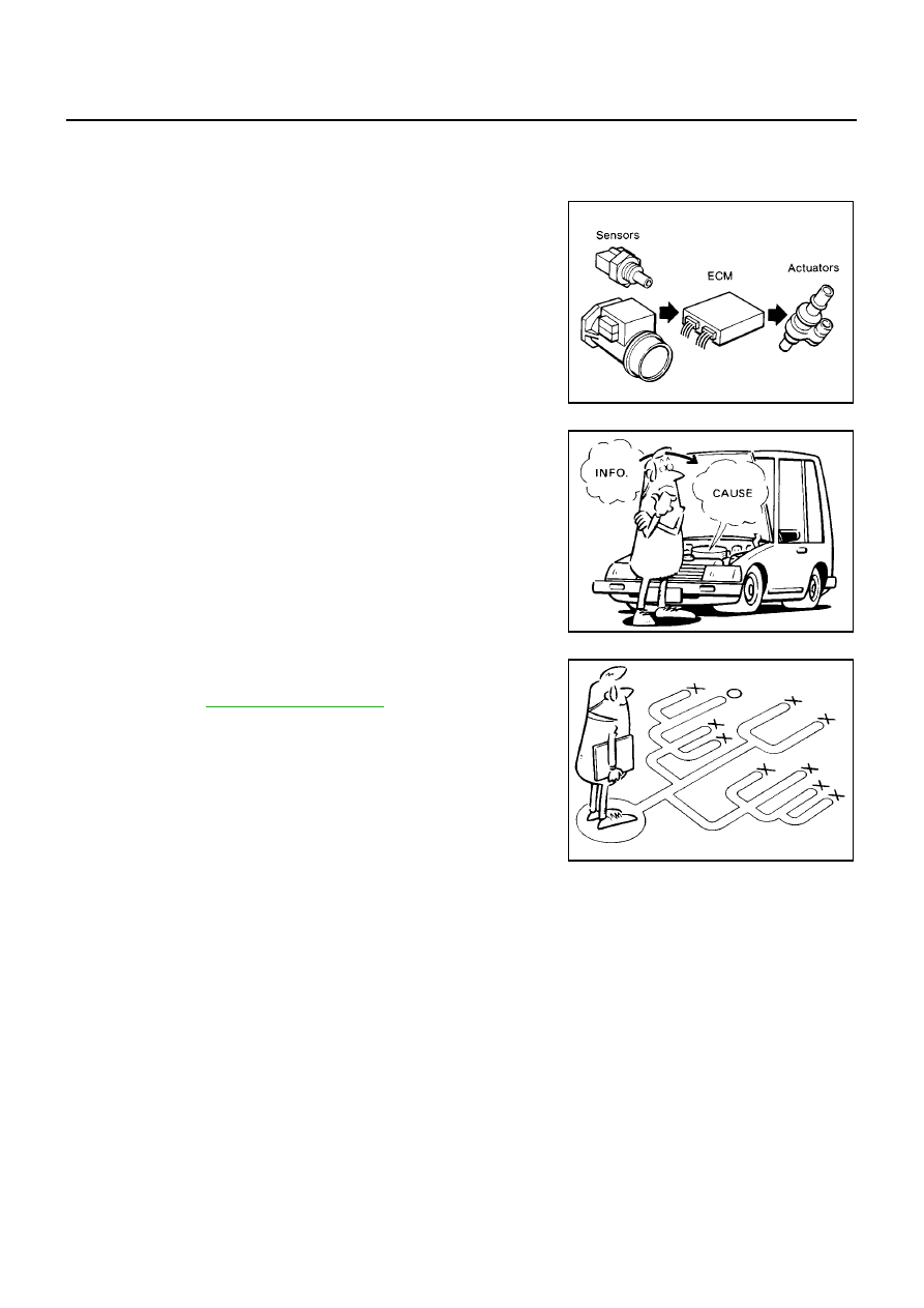
The engine has an ECM to control major systems such as fuel injec-
tion control, fuel injection timing control, glow control system, etc.
The ECM accepts input signals from sensors and instantly actuators.
It is essential that both input and output signals are proper and sta-
ble. At the same time, it is important that there are no malfunctions
such as vacuum leaks, or other malfunctions with the engine.
It is much more difficult to diagnose a malfunction that occurs inter-
mittently rather than continuously. Most intermittent malfunctions are
caused by poor electric connections or improper wiring. In this case,
careful checking of suspected circuits may help prevent the replace-
ment of good parts.
A visual check only may not find the cause of the incidents. A road
test with CONSULT-II or a circuit tester connected should be per-
formed. Follow the
.
Before undertaking actual checks, take a few minutes to talk with a
customer who approaches with a driveability complaint. The cus-
tomer can supply good information about such incidents, especially
intermittent ones. Find out what symptoms are present and under
what conditions they occur. A Diagnostic Worksheet like the example
on next page should be used.
Start your diagnosis by looking for “conventional” incidents first. This
will help troubleshoot driveability incidents on an electronically con-
trolled engine vehicle.
MEF036D
SEF233G
SEF234G
TROUBLE DIAGNOSIS
EC-375
[YD (WITHOUT EURO-OBD)]
C
D
E
F
G
H
I
J
K
L
M
A
EC
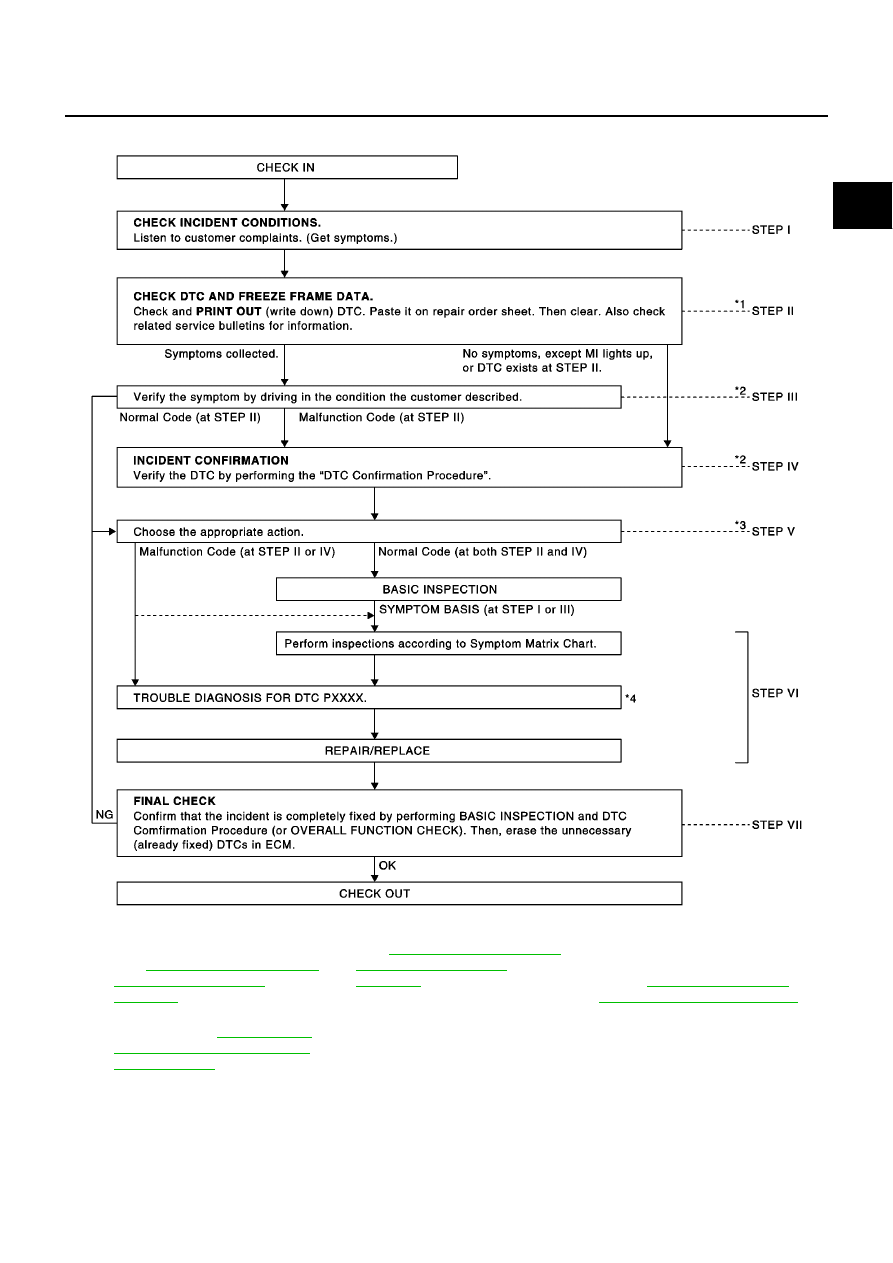
WORK FLOW
*1
If time data of “SELF-DIAG
RESULTS” is other than “0”, per-
form
SIS FOR INTERMITTENT
INCIDENT"
.
*2
If the incident cannot be verified, per-
form
SIS FOR INTERMITTENT
INCIDENT"
.
*3
If the on board diagnostic system
cannot be performed, check main
power supply and ground circuit.
Refer to
.
*4
If malfunctioning part cannot be
detected, perform
BLE DIAGNOSIS FOR INTERMIT-
TENT INCIDENT"
.
PBIB0477E
EC-376
[YD (WITHOUT EURO-OBD)]
TROUBLE DIAGNOSIS
Description for Work Flow
DIAGNOSTIC WORK SHEET
There are many operating conditions that lead to the malfunction of
engine components. A good grasp of such conditions can make trou-
bleshooting faster and more accurate.
In general, each customer feels differently about an incident. It is
important to fully understand the symptoms or conditions for a cus-
tomer complaint.
Utilize a diagnostic worksheet like the one shown below in order to
organize all the information for troubleshooting.
STEP
DESCRIPTION
STEP I
Get detailed information about the conditions and the environment when the incident/symptom occurred using the
EC-376, "DIAGNOSTIC WORK SHEET"
.
STEP II
Before confirming the concern, check and write down (print out using CONSULT-II) the DTC and the freeze frame
data, then erase the DTC. The DTC and the freeze frame data can be used when duplicating the incident at STEP III
& IV. Refer to
.
If the incident cannot be verified, perform
EC-408, "TROUBLE DIAGNOSIS FOR INTERMITTENT INCIDENT"
.
Study the relationship between the cause, specified by DTC, and the symptom described by the customer. (The
“Symptom Matrix Chart” will be useful. Refer to
.) Also check related service bulletins for information.
STEP III
Try to confirm the symptom and under what conditions the incident occurs.
The “DIAGNOSTIC WORK SHEET” and the freeze frame data are useful to verify the incident. Connect CONSULT-II
to the vehicle in DATA MONITOR (AUTO TRIG) mode and check real time diagnosis results.
If the incident cannot be verified, perform
EC-408, "TROUBLE DIAGNOSIS FOR INTERMITTENT INCIDENT"
.
If the malfunction code is detected, skip STEP IV and perform STEP V.
STEP IV
Try to detect the DTC by driving in (or performing) the DTC Confirmation Procedure. Check and read the DTC and the
freeze frame data by using CONSULT-II.
During the DTC verification, be sure to connect CONSULT-II to the vehicle in DATA MONITOR (AUTO TRIG) mode
and check real time diagnosis results.
If the incident cannot be verified, perform
EC-408, "TROUBLE DIAGNOSIS FOR INTERMITTENT INCIDENT"
.
In case the DTC Confirmation Procedure is not available, perform the Overall Function Check instead. The DTC can-
not be displayed by this check, however, this simplified “check” is an effective alternative.
The “NG” result of the Overall Function Check is the same as the DTC detection.
STEP V
Take the appropriate action based on the results of STEP I through IV.
If the malfunction code is indicated, proceed to Trouble Diagnosis for DTC PXXXX.
If the normal code is indicated, proceed to the Basic Inspection,
. Then perform inspections according to the
Symptom Matrix Chart. Refer to
.
STEP VI
Identify where to begin diagnosis based on the relationship study between symptom and possible causes. Inspect the
system for mechanical binding, loose connectors or wiring damage using (tracing) Harness Layouts.
Gently shake the related connectors, components or wiring harness with CONSULT-II set in “DATA MONITOR (AUTO
TRIG)” mode.
Check the voltage of the related ECM terminals or monitor the output data from the related sensors with CONSULT-II.
Refer to
or
.
The Diagnostic Procedure in EC section contains a description based on open circuit inspection. A short circuit
inspection is also required for the circuit check in the Diagnostic Procedure. For details, refer to
form Efficient Diagnosis for an Electrical Incident"
, “Circuit Inspection”.
Repair or replace the malfunction parts.
If the malfunctioning part cannot be detected, perform
EC-408, "TROUBLE DIAGNOSIS FOR INTERMITTENT INCI-
.
STEP VII
Once you have repaired the circuit or replaced a component, you need to run the engine in the same conditions and
circumstances which resulted in the customer's initial complaint.
Perform the DTC Confirmation Procedure and confirm the normal code (DTC P0000) is detected. If the incident is still
detected in the final check, perform STEP VI by using a different method from the previous one.
Before returning the vehicle to the customer, be sure to erase the unnecessary (already fixed) DTC in ECM. (Refer to
.)
SEF907L
Нет комментариевНе стесняйтесь поделиться с нами вашим ценным мнением.
Текст