Nissan Primera P12. Manual — part 317
DTC P0192, P0193 FRP SENSOR
EC-453
[YD (WITHOUT EURO-OBD)]
C
D
E
F
G
H
I
J
K
L
M
A
EC
DTC Confirmation Procedure
EBS0155K
NOTE:
If DTC Confirmation Procedure has been previously conducted, always turn ignition switch OFF and wait at
least 10 seconds before conducting the next test.
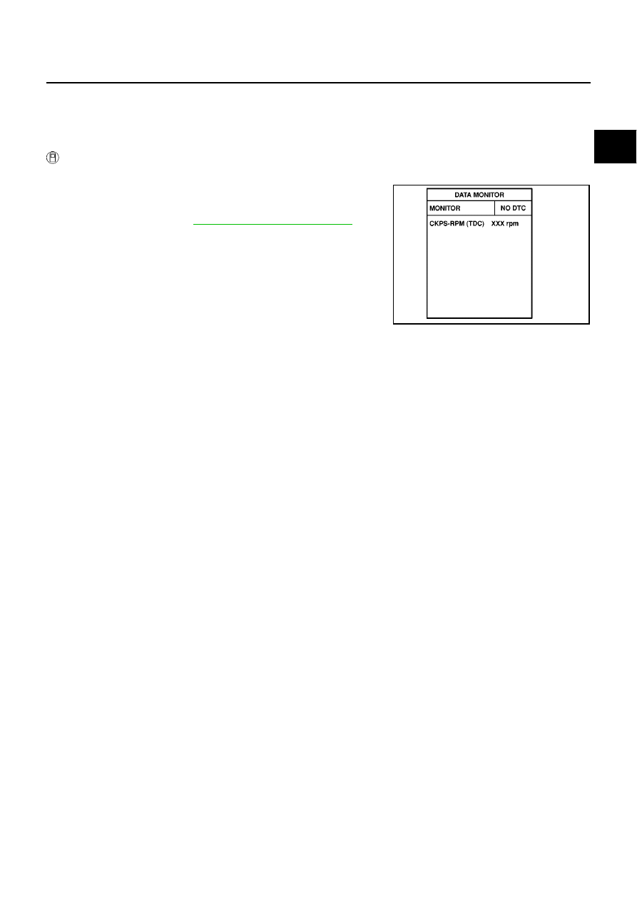
WITH CONSULT-II
1.
Turn ignition switch ON.
2.
Select “DATA MONITOR” mode with CONSULT-II.
3.
Wait at least 5 seconds.
4.
If DTC is detected, go to
EC-455, "Diagnostic Procedure"
.
SEF817Y
EC-454
[YD (WITHOUT EURO-OBD)]
DTC P0192, P0193 FRP SENSOR
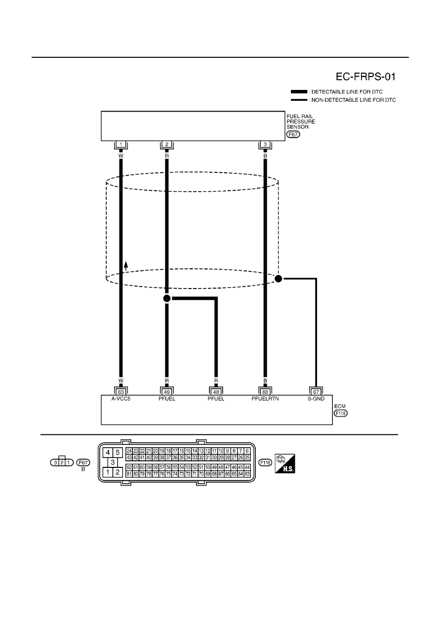
Wiring Diagram
EBS0155L
MBWA0375E
DTC P0192, P0193 FRP SENSOR
EC-455
[YD (WITHOUT EURO-OBD)]
C
D
E
F
G
H
I
J
K
L
M
A
EC
Diagnostic Procedure
EBS0155M
1.
CHECK GROUND CONNECTION
1.
Turn ignition switch OFF.
2.
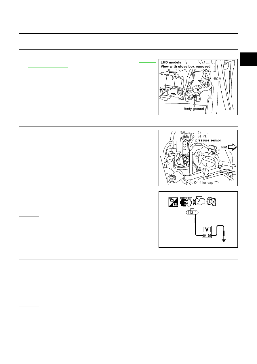
Loosen and retighten engine ground screws. Refer to
.
OK or NG
OK
>> GO TO 2.
NG
>> Repair or replace ground connections.
2.
CHECK FUEL RAIL PRESSURE SENSOR POWER SUPPLY CIRCUIT
1.
Disconnect fuel rail pressure sensor harness connector.
2.
Turn ignition switch ON.
3.
Check voltage between fuel rail pressure sensor terminal 1 and
ground with CONSULT-II or tester.
OK or NG
OK
>> GO TO 3.
NG
>> Repair open circuit or short to ground or short to power
in harness or connectors.
3.
CHECK FUEL RAIL PRESSURE SENSOR GROUND CIRCUIT FOR OPEN AND SHORT
1.
Turn ignition switch OFF.
2.
Disconnect ECM harness connector.
3.
Check harness continuity between fuel rail pressure sensor terminal 3 and ECM terminal 68.
Refer to Wiring Diagram.
4.
Also check harness for short to ground and short to power.
OK or NG
OK
>> GO TO 4.
NG
>> Repair open circuit or short to ground or short to power in harness or connectors.
MBIB0915E
MBIB1018E
Voltage: Approximately 5.3V
PBIB0405E
Continuity should exist.
EC-456
[YD (WITHOUT EURO-OBD)]
DTC P0192, P0193 FRP SENSOR
4.
CHECK FUEL RAIL PRESSURE SENSOR INPUT SIGNAL CIRCUIT FOR OPEN AND SHORT
1.
Check harness continuity between ECM terminals 48, 49 and fuel rail pressure sensor terminal 2.
Refer to Wiring Diagram.
2.
Also check harness for short to ground and short to power.
OK or NG
OK
>> GO TO 5.
NG
>> Repair open circuit or short to ground or short to power in harness connectors.
5.
CHECK FUEL RAIL PRESSURE SENSOR
Refer to
EC-456, "Component Inspection"
.
OK or NG
OK
>> GO TO 6.
NG
>> Replace fuel rail.
6.
CHECK INTERMITTENT INCIDENT
Refer to
EC-408, "TROUBLE DIAGNOSIS FOR INTERMITTENT INCIDENT"
.
>> INSPECTION END
Component Inspection
EBS0155N
FUEL RAIL PRESSURE SENSOR
1.
Reconnect harness connector disconnected.
2.
Start engine and warm it up to normal operating temperature.
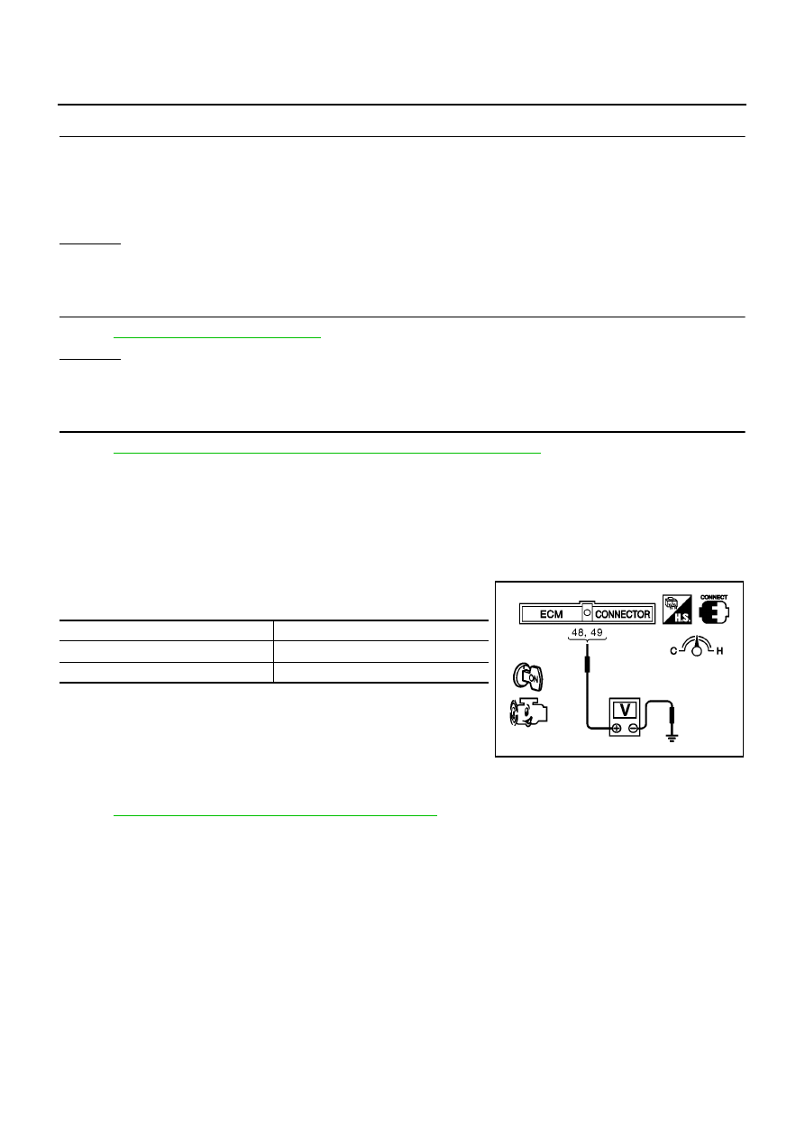
3.
Check voltage between ECM terminals 48, 49 (Fuel rail pres-
sure sensor signal) and ground under the following conditions.
4.
If the voltage is out of specification, disconnect fuel rail pressure
sensor harness connector and connect it again. Then repeat
above check.
5.
If NG, replace fuel rail.
Removal and Installation
EBS0155O
FUEL RAIL
Refer to
EM-39, "INJECTION TUBE AND FUEL INJECTOR"
.
Continuity should exist.
Condition
Voltage V
Idle
1.7 - 2.0
2,000 rpm
2.0 - 2.3
MBIB0613E
Нет комментариевНе стесняйтесь поделиться с нами вашим ценным мнением.
Текст