Nissan Primera P12. Manual — part 112
NATS (NISSAN ANTI-THEFT SYSTEM)
BL-157
C
D
E
F
G
H
J
K
L
M
A
B
BL
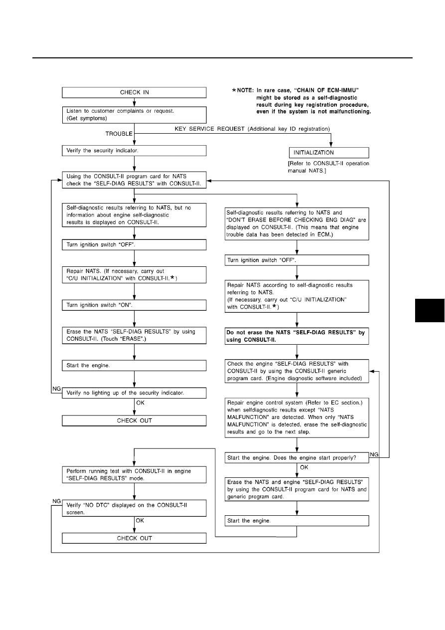
Work Flow
EIS005JB
SEL729WE
BL-158
NATS (NISSAN ANTI-THEFT SYSTEM)
Trouble Diagnoses
EIS005JC
First perform the “SELF-DIAG RESULTS” in “SMART ENTRANCE” with CONSULT-II, when perform the each
trouble diagnosis. Refer to
NATS (NISSAN ANTI-THEFT SYSTEM)
BL-159
C
D
E
F
G
H
J
K
L
M
A
B
BL
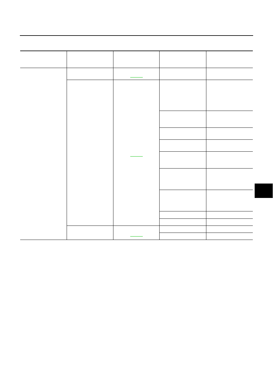
SYMPTOM MATRIX CHART 1
Self-diagnosis related item
SYMPTOM
Displayed “SELF-DIAG
RESULTS” on CON-
SULT-II screen.
DIAGNOSTIC PROCE-
DURE
(Reference page)
SYSTEM
(Malfunctioning part or
mode)
REFERENCE PART NO.
OF ILLUSTRATION ON
SYSTEM DIAGRAM
●
Security indicator
lighting up*
●
Engine cannot be
started
ECM INT CIRC-IMMU
PROCEDURE 1
(
)
ECM
B
CHAIN OF ECM-IMMU
PROCEDURE 2
(
)
In rare case, “CHAIN OF
ECM-IMMU” might be
stored during key regis-
tration procedure, even if
the system is not mal-
functioning.
—
Open circuit in battery
voltage line of IMMU cir-
cuit
C1
Open circuit in ignition
line of IMMU circuit
C2
Open circuit in ground
line of IMMU circuit
C3
Open circuit in communi-
cation line between
IMMU and ECM
C4
Short circuit between
IMMU and ECM commu-
nication line and battery
voltage line
C4
Short circuit between
IMMU and ECM commu-
nication line and ground
line
C4
ECM
B
IMMU
A
DIFFERENCE OF KEY
PROCEDURE 3
(
)
Unregistered key
D
IMMU
A
BL-160
NATS (NISSAN ANTI-THEFT SYSTEM)
*: When NATS detects trouble, the security indicator lights up while ignition key is in the “ON” position.
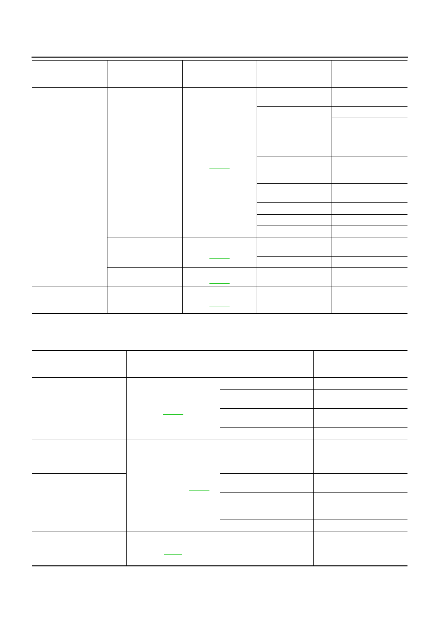
SYMPTOM MATRIX CHART 2
Non self-diagnosis related item
*: CONSULT-II Self-diagnostic results display screen “no malfunction is detected”.
SYMPTOM
Displayed “SELF-DIAG
RESULTS” on CON-
SULT-II screen.
DIAGNOSTIC PROCE-
DURE
(Reference page)
SYSTEM
(Malfunctioning part or
mode)
REFERENCE PART NO.
OF ILLUSTRATION ON
SYSTEM DIAGRAM
●
Security indicator
lighting up*
●
Engine cannot be
started
CHAIN OF IMMU-KEY
PROCEDURE 4
(
)
Malfunction of key ID
chip
E5
Communication line
between ANT/ AMP and
IMMU:
Open circuit or short cir-
cuit of battery voltage
line or ground line
E1
E2
Open circuit in power
source line of ANT/ AMP
circuit
E3
Open circuit in ground
line of ANT/ AMP circuit
E4
Antenna amp.
E6
Dongle unit
G
IMMU
A
ID DISCORD, IMM-ECM
PROCEDURE 5
(
)
System initialization has
not yet been completed.
F
ECM
B
LOCK MODE
PROCEDURE 7
(
)
LOCK MODE
D
Security indicator light-
ing up*
DON'T ERASE
BEFORE CHECKING
ENG DIAG
WORK FLOW
(
)
Engine trouble data and
NATS trouble data have
been detected in ECM
—
SYMPTOM
DIAGNOSTIC PROCEDURE
(Reference page)
SYSTEM
(Malfunctioning part or mode)
REFERENCE PART NO. OF
ILLUSTRATION ON SYSTEM
DIAGRAM
Security ind. does not light up.
PROCEDURE 6
)
Security ind.
—
Open circuit between Fuse and
IMMU
—
Continuation of initialization
mode
—
IMMU
A
Security ind. does not blink just
after initialization even if the
vehicle is equipped with don-
gle unit.
PROCEDURE 8
(RHD models only:
)
NATS might be initialized with-
out connecting dongle unit
properly.
—
Security ind. does not blink just
after ignition switch is turned to
ON when some malfunction
related to NATS is detected
even if the vehicle is equipped
with dongle unit.
Open circuit in ground line of
dongle unit circuit
C6
Open or short circuit in commu-
nication line between IMMU
and dongle unit
C5
Dongle unit
G
Security ind. dose not blink just
after ignition switch is turned to
ON.
Engine can not be started*
PROCEDURE 9
)
Open or short circuit starter
motor between smart entrance
control unit
—
Нет комментариевНе стесняйтесь поделиться с нами вашим ценным мнением.
Текст